


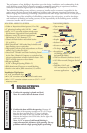
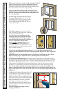
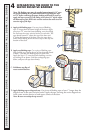
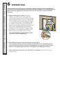
Applications for Performance Upgrade and HurricaneShield:
6"
16" MAX
O.C.
16" MAX
O.C.
16" MAX
O.C.
16" MAX
O.C.
6"
6"
6"
6"
6" 6"
6"
DOUBLE OPERABLE
6"
6"
16"
MAX.
O.C.
2C
6"
6"
16"
MAX.
O.C.
2C
2C
5E
16" MAX
O.C.
16" MAX
O.C.
6"
6"
6" 6"
SINGLE FIXED OR OPERABLE
6"
6"
16"
MAX.
O.C.
6"
6"
16"
MAX.
O.C.
2C
2C
2C
5E
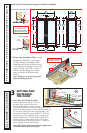
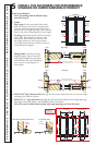
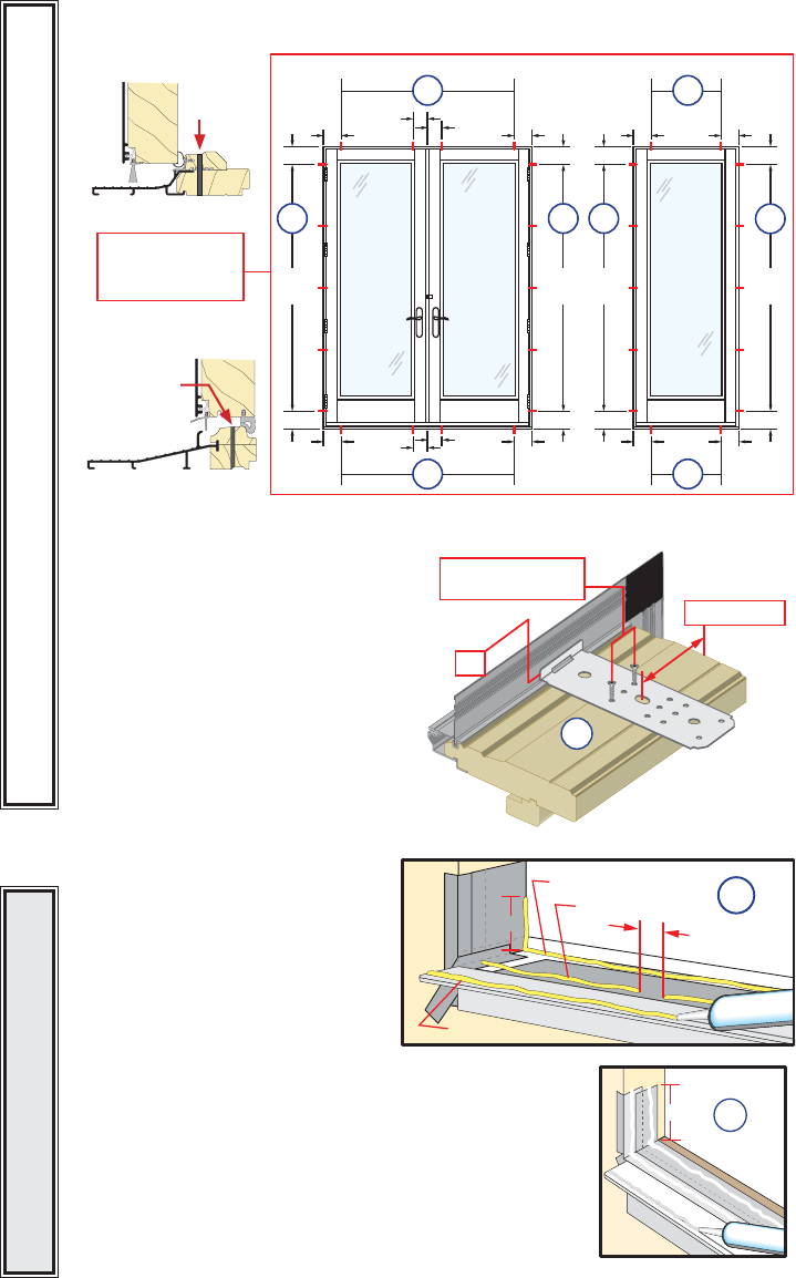
DIAGRAM FOR
PLACEMENT OF
THRESHOLD SCREWS &
INSTALLATION CLIPS
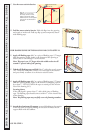
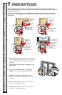
C. Doors using Installation Clips: Install
installation clips. Place each clip so
the lip is facing up and against the
installation n at the locations shown
in the placement diagram. Secure each
clip by driving a #6 x 5/8” corrosion
resistant screw through each of the
outer two holes of the three holes
shown.
Note: If clips are to be bent; pre-bend
before attaching to frame.
6“ from end
Lip
#6 x 5/8” corrosion
resistant screws
2C
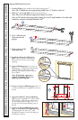
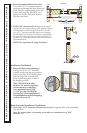
3
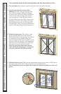
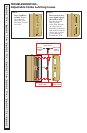
SETTING AND
FASTENING
THE DOOR
A. Place three 3/8” beads of sealant.
Place the rst beads sealant ½” from
the base of the interior sill pan lip.
is bead should also continue up the
corner of the sill pan at each end, sealing the vertical
joints of the sill pan legs. Continue the rst bead up
6” onto each jamb side of the rough opening. e
second bead should be approximately ½” from the
exterior edge of the rough opening, running from
jamb to jamb with a 2” break in the middle of the
opening. Place a third sealant bead in the groove
of the sill support from end to end or ¼” from the
exterior edge of the wood blocking.
Note: Sill sealant detail is the same for applications
with and without optional sill pan.
3A
1
2
3
6”
PERFORMANCE UPGRADE & HURRICANESHIELD DOORSALL DOORS • ALL DOORS
EXTERIOR SILL PAN LIP
INTERIOR SILL PAN LIP
2nd Bead
Leave a 2" break
in center of pan
1st Bead
3rd Bead
3A
6”
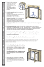
Out-Swing Vent or Fixed
In-Swing Vent
Out-Swing Vent or Fixed
In-Swing Vent
Out-Swing Vent and Fixed
In-Swing Vent
Screw
Location
Screw
Location
Applications without sill pan