


Pelco Manual C314M-D (8/98) 7
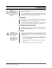
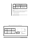
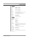
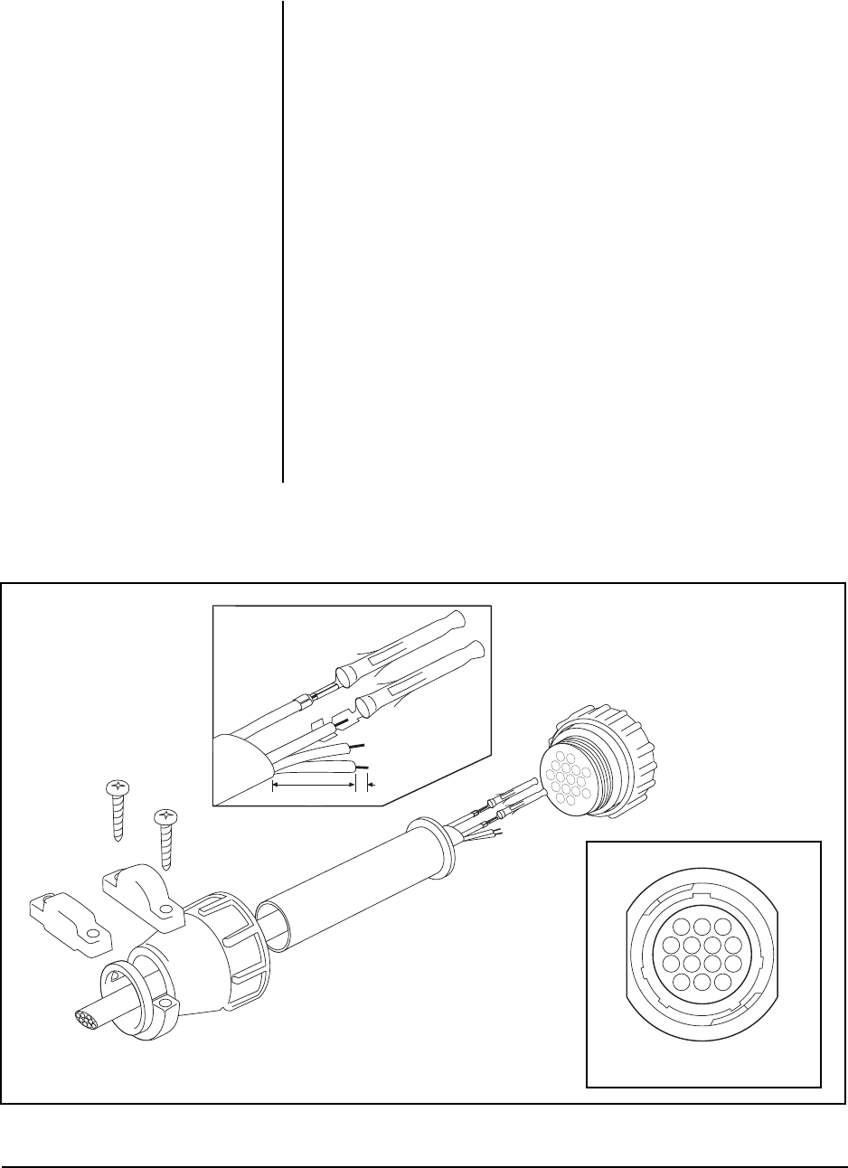
Figure 1. Connector Assembly
OR
00009
1"
1/8"
A
B
FRONT VIEW
00002
13
47
811
1214
14-PIN
NOTE:
Contacts cannot be re-
moved from the connector without
the use of the appropriate AMP ex-
traction tool (ZT305183), which is
available from Pelco.
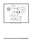
NOTE:
When a pan/tilt is mounted
in the inverted position, the LEFT/
RIGHT and UP/DOWN functions
are reversed during operation. To
correct this problem, reverse the
LEFT/RIGHT functions in the con-
trol cable (pins 3 and 7) at the pan/
tilt or control and the UP/DOWN
functions (pins 5 and 6) at the pan/
tilt or control.
3.3.1 Mating Connector Assembly
To assemble the mating connector, refer to Figure 1 and perform the following steps.
1. Slide the connector clamp assembly over the conductor cable. If the diameter
of the conductor cable is such that the rubber boot will slide over it easily, slide
the rubber boot onto the conductor cable at this time. If not, discard the rubber
boot.
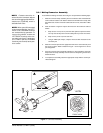
2. Refer to Detail A in Figure 2. Prepare the wires from the conductor cable as
follows:
a. Strip at least 1-inch (2.54 cm) from the cable jacket to expose the wires.
You may need to strip more from the cable jacket if you have more wires.
b. Strip 1/8-inch (0.125 cm) from each wire.
c. Using an AMP style crimper, crimp the wires and their insulation to the
connector pins.
3. Slide the connector pins into the appropriate holes in the connector body until
they snap into place. Refer to detail B in Figure 1 and to Figure 2 for correct
pin arrangement.
4. Push the connector clamp assembly (with boot, if used) toward the connector
body. Screw the clamp assembly onto the connector body, being careful not to
disturb the wires.
5. To complete the assembly, attach the appropriate clamp with the screws pro-
vided and tighten.