


2 Pelco Manual C314M-D (8/98)
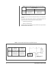
REVISION HISTORY
Manual # Date Comments
C314M-D 8/98 Changed manual to new format. Added certifications. Re-
vised installation instructions. Moved exploded assembly
diagram and parts lists to maintenance/service manual.
Revised Troubleshooting and Maintenance sections.
CONTENTS
Section Page
1.0 GENERAL ..................................................................................................3
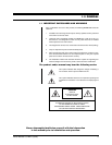
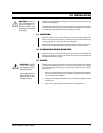
1.1 IMPORTANT SAFEGUARDS AND WARNINGS ...............................3
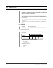
2.0 DESCRIPTION ..........................................................................................4
2.1 MODELS ............................................................................................4
2.2 CERTIFICATIONS .............................................................................4
3.0 INSTALLATION ........................................................................................... 5
3.1 MOUNTING .......................................................................................5
3.2 CAMERA/ENCLOSURE MOUNTING ...............................................5
3.3 WIRING .............................................................................................5
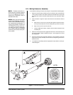
3.3.1 Mating Connector Assembly ...................................................7
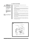
3.4 LIMIT/STOP ADJUSTMENT ..............................................................9
4.0 OPERATION .............................................................................................10
5.0 TROUBLESHOOTING ..............................................................................11
5.1 SERVICE MANUAL ..........................................................................11
6.0 MAINTENANCE ........................................................................................12
6.1 TIGHTENING DRIVE CHAINS .........................................................12
6.2 CHAIN DRIVE LUBRICATION ..........................................................12
7.0 SPECIFICATIONS ....................................................................................13
8.0 WARRANTY AND RETURN INFORMATION ...........................................16
LIST OF ILLUSTRATIONS
Figure Page
1 Connector Assembly ..........................................................................7
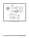
2 PT180-24P/PT180-24SL Wiring Diagram ..........................................8
3 Limit Stops .........................................................................................9
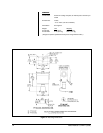
4 Mounting Dimensions .......................................................................14
LIST OF TABLES
Table Page
A Maximum Cable Distances to Wire Pan and Tilt Motors ....................6
B Recommended Cable Distances Using RB24 Relay Box ..................6