22 C2655M-A (10/08)
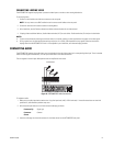
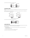
Figure 19 illustrates the wiring configuration for supervised alarm inputs.
Figure 19. Supervised Alarm Input Wiring
UNSUPERVISED ALARMS
When an alarm is configured as an unsupervised alarm, the NET5308T-EXP triggers an alarm only when the normal alarm state (open or closed)
changes.
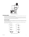
Figure 20 illustrates the alarm and no alarm conditions of an unsupervised alarm input. A normally closed alarm input can be defeated with a
bypass. A normally open input can be defeated with a cut.
Figure 20. Unsupervised Alarm Conditions
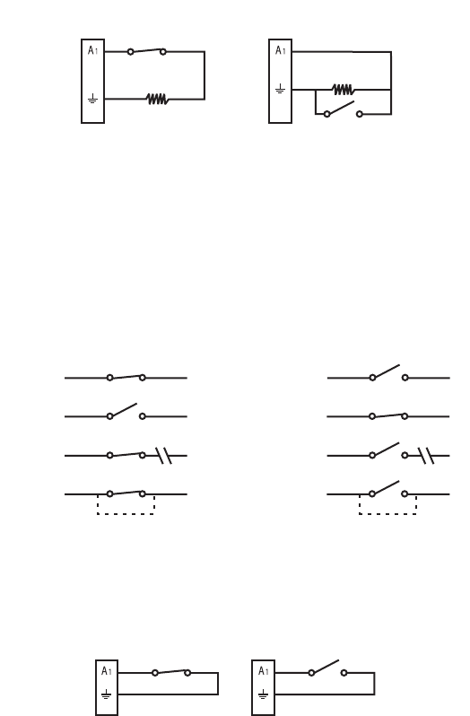
Figure 21 illustrates the wiring configuration for unsupervised alarm inputs.
Figure 21. Unsupervised Alarm Input Wiring
ALARM CONNECTIONS
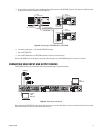
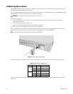
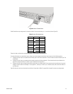
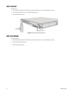
The unit includes two 8-pin alarm terminal blocks. These blocks have tension clamps. Use a small screwdriver to open the clamp for a particular
lead. Figure 22 shows how to wire the alarm terminal block and connect it to the NET5308T-EXP.
When wiring the connector:
• Use 20 to 28 AWG (0.08 to 0.5 mm
2
) wire that is rated for 250 V or higher. The insulation must be thick enough to protect against
electrostatic discharge (ESD).
• Strip the alarm wire to 0.31 inches (8 mm).
• Insert the wire far enough into the connector so that the metal is not exposed.
The terminal block is keyed. It attaches only one way to the NET5308T-EXP.
NORMALLY CLOSED NORMALLY OPEN
10 K
Ω
10 K
Ω
NORMALLY OPEN
NORMALLY CLOSED
ALARM
GND
+V
+V
ALARM
GND
+V
+V
NO ALARM
GND
ALARM
GND
+V
+V
+V
NO ALARM
GND
CUT
BYPASS
CUT
NO ALARM
GND
NO ALARM
GND
+V
BYPASS
ALARM
GND
NORMALLY CLOSED NORMALLY OPEN


