


12 C1517M-A (11/02)
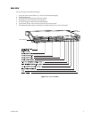
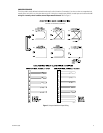
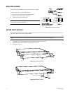
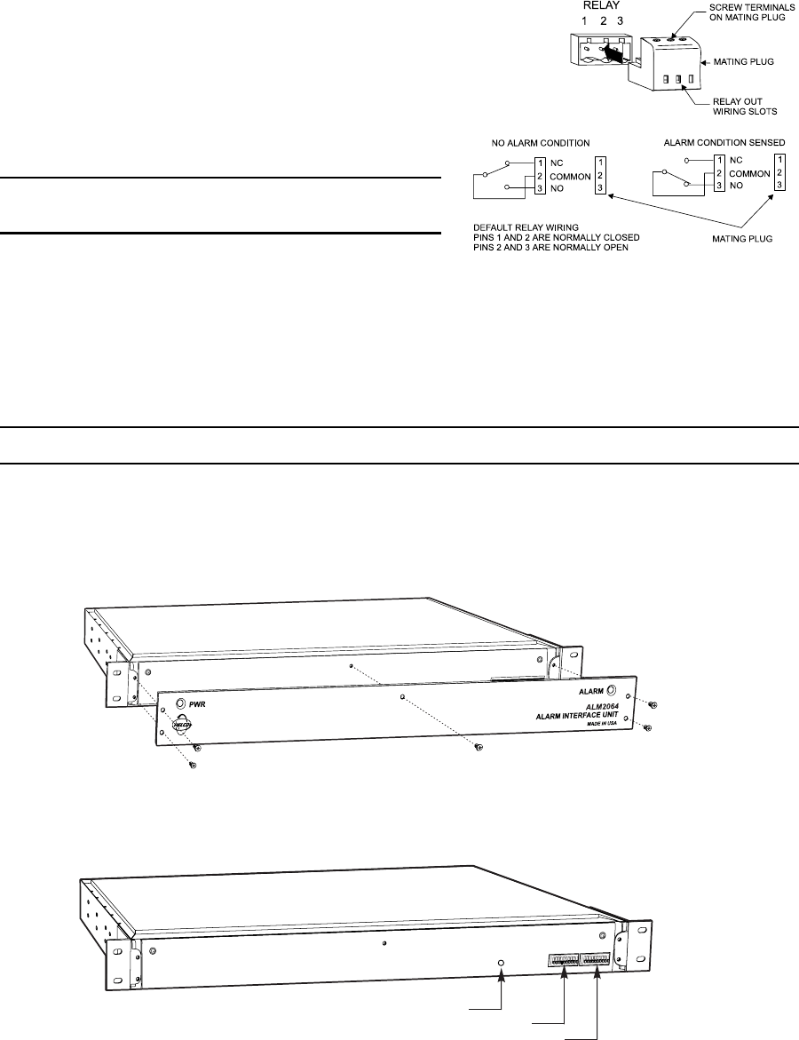
RELAY OUTPUT WIRING
The alarm unit activates the relay when a valid alarm condition is sensed.
To wire the relay output, you must do the following:
1. Remove the mating plug from the relay output connector.
2. Place the wires into the relay out wiring slots.
3. Tighten the screws to secure the wires.
NOTE: Refer to the REL2064 Installation/Operation Manual for instructions
on wiring relays to peripheral equipment.
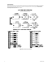
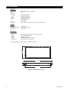
Figure 10. Relay Output Connector
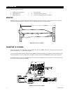
Figure 11. Front Panel Removal
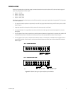
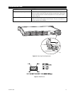
Figure 12. DIP Switch Location
DIP SWITCH 1
RESET SWITCH ACCESS
DIP SWITCH 2
00717
00716
00715
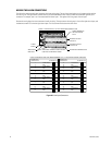
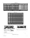
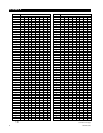
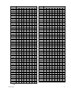
SETTING THE DIP SWITCHES
The positioning of the DIP switches for SW1 and SW2 determines how your alarm unit operates. You are able to set the baud rate, alarm
range, alarm group and mode, and local device address.
NOTE: You must recycle power if you make changes to the DIP switches after the alarm unit has been turned on.
1. Remove the front panel by unscrewing the five flat-head Phillips screws. Refer to Figure 11.
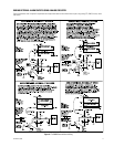
2. Set the DIP switches. Refer to Tables A and B and Figures 12 and 13.
3. Replace the front panel.