


10 C1517M-A (11/02)
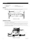
MAKING THE ALARM CONNECTIONS
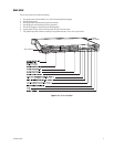
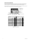
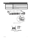
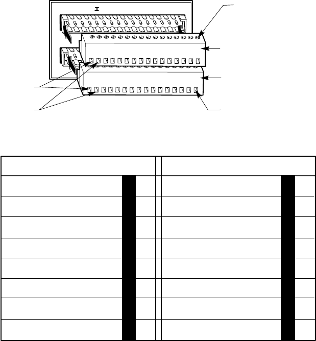
Each of the four groups contains two connectors with input mating plugs. The top of each mating plug has 16 screw terminals and the
front has 16 pins. The figure below indicates how the pins alternate between alarm inputs and their associated GND (ground) input
connection. For example, pins 1 and 2 are associated with alarm input 1. This applies to all four groups of alarm inputs.
Remove the mating plugs from the connectors to install the wiring. The top connector of each group is for the first eight alarm inputs, and
the bottom connector is for the last eight alarm inputs. The 16 screw terminals secure the alarm wires.
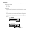
Figure 8. Alarm Input Connectors
17 18 19 20 21 22 23 24 25 26 27 28 29 30 31 32
1 2 3 4 5 6 7 8 9 10 11 1213 14
15 16
GROUP 1 ALARM INPUTS (1-16) WITH REMOVABLE MATING PLUGS
SCREW TERMINALS
ON EACH MATING
PLUG
MATING PLUG FOR
INPUTS 1-8
MATING PLUG FOR
INPUTS 9-16
ALARM INPUT WIRING SLOTS
ADDITIONAL MATING PLUGS SUPPLIED
FOR EACH ALARM INPUT GROUP
1
8
ALARM
INPUTS
ASSOCIATED
GND INPUT
NOTE: THE MATING PLUGS HAVE BEEN NUMBERED (1-16, 17-32) FOR DISCUSSION PURPOSES.
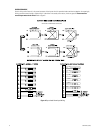
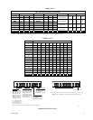
MATING PLUG
HEADER PIN # ALARM INPUT #
1ALARM INPUT 1
2 GND
3ALARM INPUT 2
4 GND
5ALARM INPUT 3
6 GND
7ALARM INPUT 4
8 GND
9ALARM INPUT 5
10 GND
11 ALARM INPUT 6
12 GND
13 ALARM INPUT 7
14 GND
15 ALARM INPUT 8
16 GND
MATING PLUG
HEADER PIN # ALARM INPUT #
17 ALARM INPUT 9
18 GND
19 ALARM INPUT 10
20 GND
21 ALARM INPUT 11
22 GND
23 ALARM INPUT 12
24 GND
25 ALARM INPUT 13
26 GND
27 ALARM INPUT 14
28 GND
29 ALARM INPUT 15
30 GND
31 ALARM INPUT 16
32 GND
00713