


Page 5Peavey Electronics Corp.
Table Of Contents
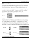
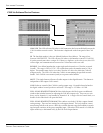
The CAB
™
components and their relationships (Figure 1)
10
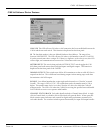
The CobraNet
™
audio transport devices and their control panels (Figure 2)
10
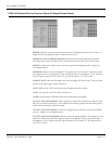
Recommended Test View Configuration (Figure 3)
11
Typical Network Connections (Figure 4)
22
Direct Connection Example (Figure 5)
22
Analog and Digital Audio Connections (Figure 6)
23
RS-485 Serial Data Connections (Figure 7)
23
CAB 16i Link Connection Example (Figure 13)
28
CAB 16o Link Connection Example (Figure 14)
29
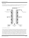
Hardware Base Address Switches (Figure 16)
30
Hardware & Software Addressing Controls (Figure 17)
30
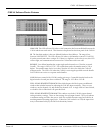
CobraNet Input and Output Controls (Bundle Numbers in the OFF position) (Figure 18)
31
CAB Device Audio Bundle Number controls shown in the OFF position. (Figure 19)
31
Test Configuration (CAB 16i, CAB 16o)
32-33
Test Configuration (CAB 16d)
34-35
Illustrations
CAB 16d Link Connection Example (Figure 15)
29
Standard “normal” CAT 5 cable (Figure 9)
26
S/PDIF resistor network configurations (Figure 8)
25
CAT 5 Wire/Connector cross reference chart, standard & crossover cable types (Figure 10)
27
CAT 5 cable and RJ-45 termination details (Figure 11)
27
CAT 5 “crossover” cable (Figure 12)
27