


CAT 5 Cables
Page 27Peavey Electronics Corp
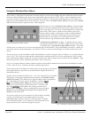
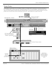
Crossover cables are used to connect switches to other switches or CAB 16s directly to the DPU card. Also, a crossover cable is
what you would use if you were to connect a CAB 16 to another CAB 16, for use as a digital “snake”. A crossover cable is termi-
nated the same way as a normal cable, except that the TX and RX pins are "swapped" at one
end to allow the transmit pair of
one device to connect to the receive pair of the other. Normally, this crossover action is done within the switch, which is why
you use a straight-through cable most of the time.
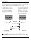
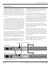
It is very easy to tell the difference between a crossover cable and a straight-through cable by looking at the conductors in the
RJ-45 connectors. If the wiring is identical at both ends, you are looking at a straight-through cable. If it is different, you most
likely have a crossover cable, or possibly, an incorrectly terminated cable. Look carefully at the color of the conductors.
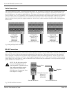
It is important to note that some switches include “uplink” ports. These ports are intended to serve as a connection to another
switch. As such, the uplink port is wired to use a straight-through cable instead of requiring a crossover cable. On some switch-
es, uplink ports share their connection with an adjacent port, so be sure to read the manufacturer's instructions for proper use.
White w/blue stripe
Blue w/white stripe
White w/orange stripe
Orange w/white stripe
White w/green stripe
Green w/white stripe
White w/brown stripe
Brown w/white stripe
Conductor
1
1
2
2
3
3
4
4
Wire Pair
5
4
1 (3 x-over)
2 (6 x-over)
3 (1 x-over)
6 (2 x-over)
7
8
Connector Pin
Not used
Not used
TX +
TX -
RX +
RX -
Not used
Not used
Function
TX Pair
Pins (1-8)
RX Pair
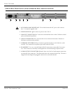
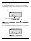
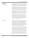
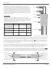
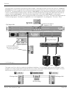
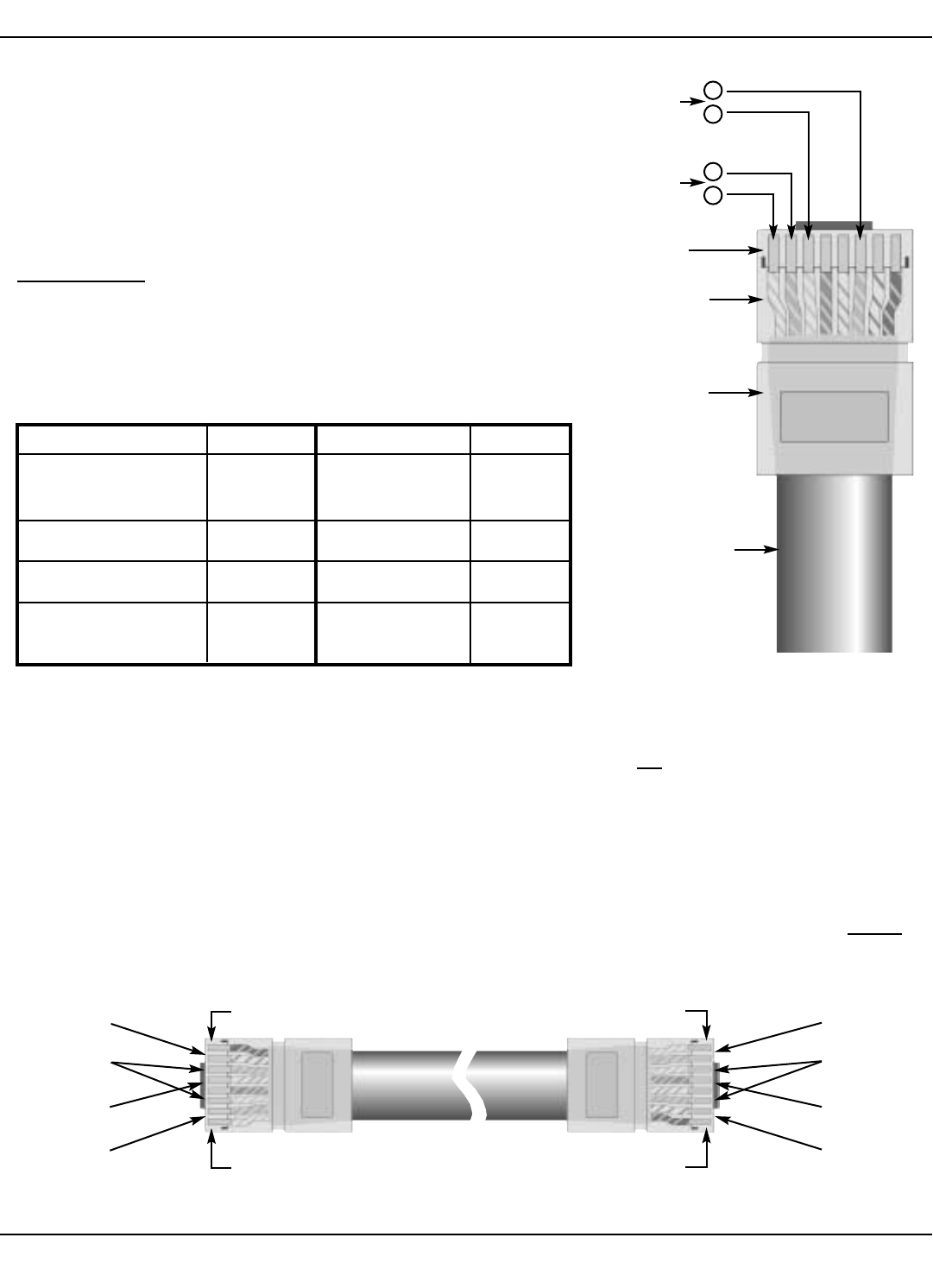
Remember, for ethernet, the BLUE and BROWN pairs are not used. The
ORANGE pair is transmit (TX), and the GREEN pair is receive (RX). There
is a positive and negative conductor for each pair, indicated by the color code.
Notice on the chart that the order of the wire pairs does not follow the con-
nector pins, as mentioned earlier. Don’t let that confuse you. The first wire of
a given pair is always the white wire with a colored stripe and is the positive
conductor. The corresponding colored wire with the white stripe is the nega-
tive conductor for that pair.
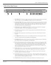
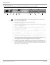
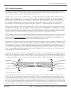
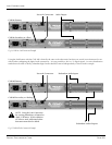
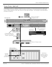
Crossover Cables
Normal CAT 5 cables are designed to connect the CAB
™
16 to a network
switch only. You cannot use this type of cable to connect a CAB 16 directly to
a MediaMatrix MM-DSP-cn DPU card. For that you need a “crossover” cable.
The pin assignments for a crossover cable, shown in parentheses on the chart,
apply to ONE END of the cable ONLY!
+
-
Conductors
RJ-45 Shell
Jacketed Cable
+
-
Fig. 12, CAT 5 “crossover” cable
Fig. 11, CAT 5 cable and RJ-45 termination details
Fig. 10, CAT 5 Wire/Connector cross reference chart, standard & crossover cable types.
Blue Pair
Brown Pair
Orange Pair
Green Pair
Blue Pair
Orange Pair
Green Pair
Brown Pair
Pin 1
Pin 8
Pin 8
Pin 1