CAB
™
16 Series User Manual
Page 38 http://aa.peavey.com copyright 2000 All Rights Reserved
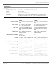
Specifications
MECHANICAL
CAB 16i & CAB 16o PERFORMANCE
CAB 16i CAB 16o
Dimensions (H x W x D)
Weight
Mounting
Connections
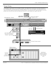
19" W x 12-7/8" D x 1-3/4" H (48.26 x 32.70 x 4.44 cm)
9.5 lbs. (4.3 kg)
Single EIA Space Rack Mount
Removable “Euro” Connectors for each single channel of audio inputs and RS-485
bus. RJ-45 for CobraNet
™
interface, BNC for link. IEC receptacle for AC power.
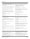
Frequency Response:
Phase Response:
THD + Noise:
Dynamic Range:
Common Mode Rejection Ratio:
Crosstalk:
Maximum Input Sensitivity Settings:
Full Scale Output Settings:
Analog Gain Range:
Input/Output Impedance:
Analog LED Metering:
+0 / -0.03 dBr, 20 ~ 20 kHz, referenced @
1 kHz.
+6 / -15 degrees at converter input
20 ~ 20 kHz, referenced @ 1 kHz.
0.005%, 22 kHz bandwidth measure-
ment, +4 dBu signal with 20 dB head-
room.
108 dB / 110 dBA, 22 kHz filter band-
width measurement.
55 dB typ.
Any gain setting.
-100 dB, 20 ~ 20 kHz, measured between
channel pairs (1-2, 3-4,…….15-16)
+30, +24, 18, +12 dBu, Less than 0.5 dB
error between settings
N/A
97.5 to +30.5 dB, 1/2 dB steps, 0.05 dB
maximum error
9.5k Ohms, minimum balanced circuit
value at any setting
16 peak-reading headroom LED meters
analog level at input of A/D. Top-most
LED indicates level 1 dB below clipping
+0 / -0.3 dBr, 20 ~ 20 kHz, referenced @
1 kHz.
+10 / -18 degrees from converter output
20 ~ 20 kHz, referenced @ 1 kHz.
0.0035%, 22 kHz bandwidth measure-
ment, +4 dBu signal with 20 dB head-
room.
110 dB / 112 dBA, 22 kHz filter band-
width measurement.
N/A
-90 dB, 20 ~ 20 kHz, measured between
channel pairs (1-2, 3-4,…….15-16)
N/A
+24, +18, +12, +6 dBu, Less than 0.5 dB
error between settings
97.5 to +30.5 dB, 1/2 dB steps, 0.05 dB
maximum error
102 Ohms, maximum balanced circuit
value at any setting
16 peak-reading headroom LED meters
output of D/A (CAB 16o). Top-most
LED indicates level 1 dB below clipping


