11
A. INTEGRAL DRAFT HOOD
1. The MI/MIH boiler is equipped with a built-in draft
hood. This device is designed to:
a. provide for the ready escape of flue gases from
the boiler in the event of no draft.
b. prevent a backdraft from entering the boiler.
c. control stack draft during operation.
These tasks are accomplished without the extra
height requirements of a separate draft hood.
2. The draft hood relief opening is the large rectangular
passage at the front of the boiler. Make certain that
there are no obstructions to airflow in front of this
opening.
3. A vent safety shut-off switch is located within the
draft relief opening to shut off the boiler in case of a
blocked vent condition. See Section 7B for details
regarding this device. See Figure 6.1 in Section 6
(Electrical) for spill switch location.
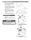
4. The vent damper can be mounted directly onto the
round draft hood outlet (vent connector) on top of
the boiler, or in vent piping close to the boiler. See
the Vent Damper Installation Instructions below.
B. VENT DAMPER INSTALLATION –
GENERAL
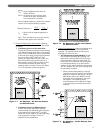
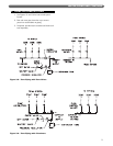
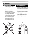
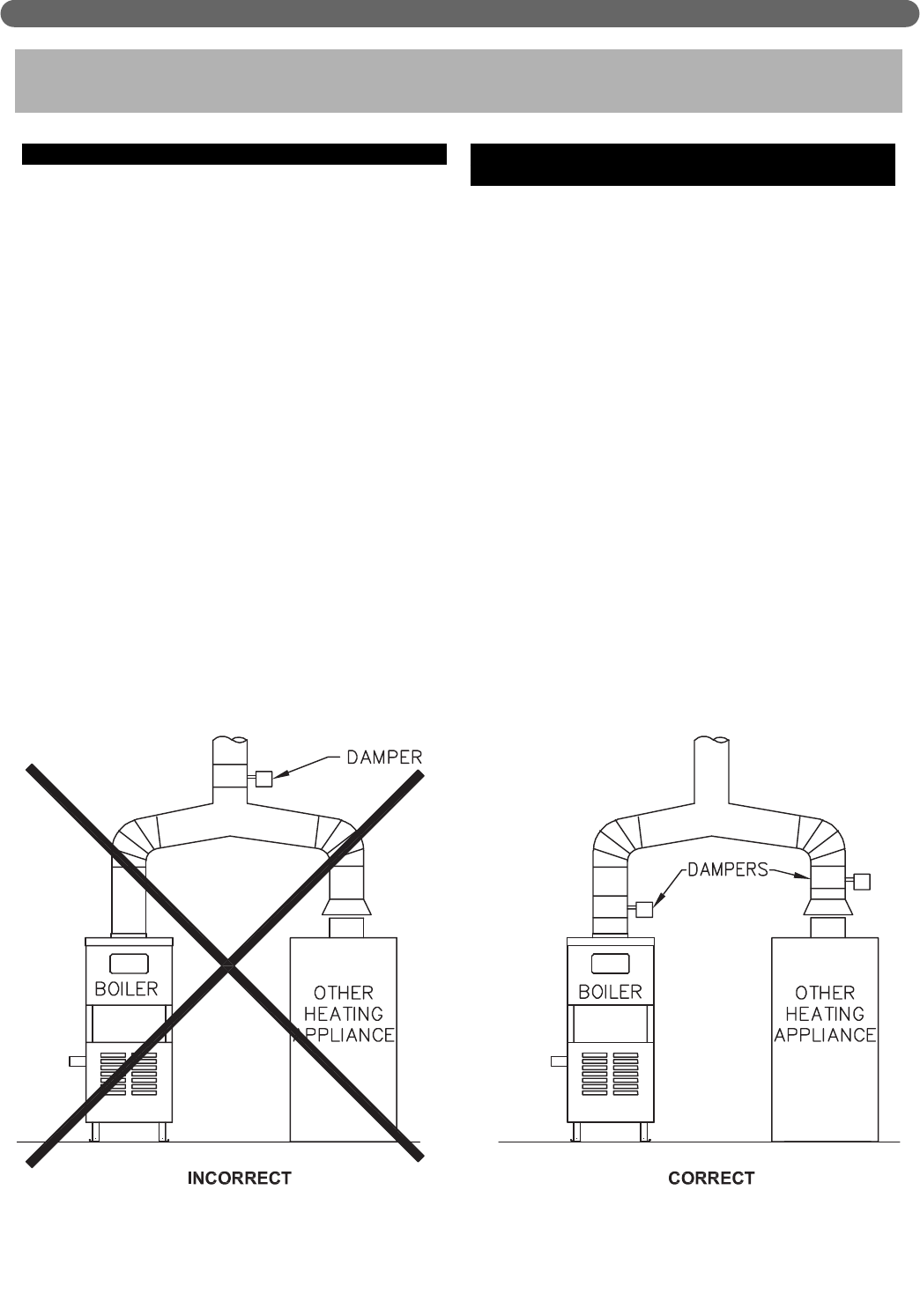
1. Do not use one vent damper to control two or more
heating appliances. See Figure 4.1.
2. Follow these and the installation instructions that are
included with the vent damper. Observe the cautions
and warnings that accompany all instructions.
3. Make certain that minimum clearances provided in
the vent damper manufacturer’s instructions are
maintained and that adequate space is available for
damper access and service.
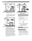
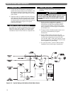
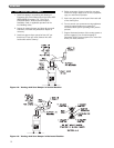
4. Orient the damper operator to facilitate connection
of the harness with the vent damper and boiler. Note
flue gas flow arrow on vent damper and orient as
required. For installation with damper mounted in
vertical position, see Figure 4.2. For installation with
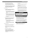
damper mounted in horizontal position, mount the
unit as shown in Figure 4.3 to avoid excessive heat
on the operator or condensation drips into the
operator.
4. VENTING
Figure 4.1: Venting Multiple Appliances
VENTING


