


23
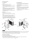
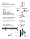
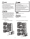
WARNING
Be sure to comply with local codes on running the
wire from the indoor unit to the outdoor unit (size
of wire and wiring method, etc.).
Each wire must be firmly connected.
No wire should be allowed to touch refrigerant
tubing, the compressor, or any moving part.
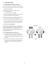
Be sure to connect power wires correctly match-
ing up numbers on terminals of the outdoor unit
and respective indoor units A – D.
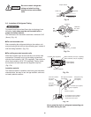
CAUTION
Be sure to connect the power supply line to the
outdoor unit as shown in the wiring diagram. The
indoor unit draws its power from the outdoor unit.
Do not run wiring for antenna, signal, or power
lines of television, radio, stereo, telephone, secu-
rity system, or intercom any closer than 3'4" (1 m)
from the power cable and wires between the
indoor and outdoor units. Electrical noise may
affect the operation.
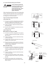
To avoid the risk of electric shock, each air conditioner
unit must be grounded.
For the installation of a grounding device, please
observe local electrical codes.
Grounding is necessary, especially for units using
inverter circuits, in order to release charged electricity
and electrical noise caused by high tension.
Otherwise, electrical shock may occur.
Place a dedicated ground more than 7' (2 m) away from
other grounds and do not have it shared with other
electric appliances.
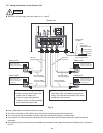
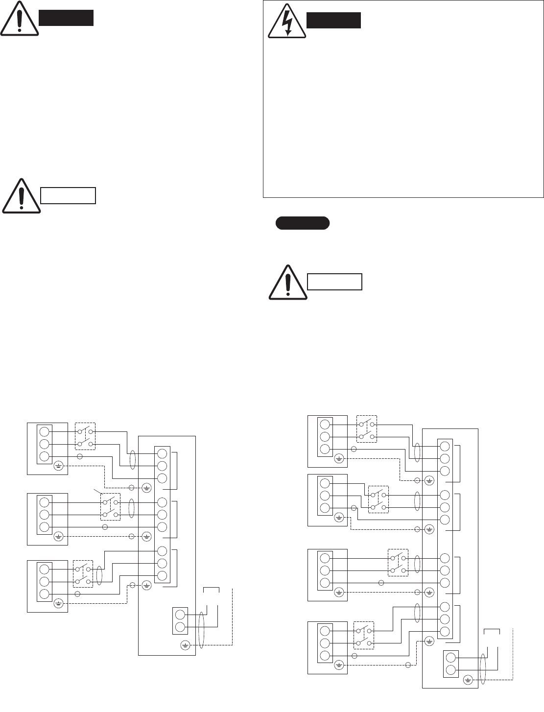
WARNING
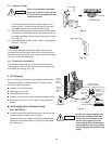
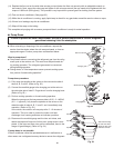
Fig. 25a
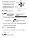
Fig. 25b
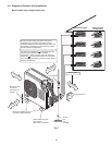
4 indoor units with CU-4KS24NBU, CU-4KS31NBU
1
2
3
Terminal
INDOOR UNIT
1
2
3
INDOOR UNIT
1
2
3
1
UNIT B
2
3
4
UNIT C
5
6
7
8
9
1
2
TerminalTerminal
L1
L2
INDOOR UNIT
UNIT A
(A)
(B)
(C)
Terminal
(2P)
Terminal
(
9P
)
OUTDOOR UNIT
Disconnect
switch
*
*
*
230/208V
230/208V
230/208V
230/208V
230/208V
230/208V
230/208V
230/208V
230/208V
Grounding
line
Grounding
line
Disconnect
switch
Field supply
Disconnect
switch
Field supply
Field supply
Power supply
Single-phase 230/208VAC 60HZ
Grounding
line
Grounding line
(A)
(B)
(B)
(B)
(B)
(B)
(B)
(C)
(C)
(C)
1
2
3
Terminal
1
UNIT B
2
3
4
UNIT C
5
6
7
UNIT D
8
9
10
11
12
1
2
L1
L2
INDOOR UNIT
UNIT A
(A)
1
2
3
Terminal
INDOOR UNIT
(B)
Terminal
(
2P
)
Terminal
(
12P
)
OUTDOOR UNIT
Disconnect
switch
230/208V
230/208V
230/208V
230/208V
230/208V
230/208V
Grounding line
Grounding line
Field supply
230/208V
230/208V
230/208V
230/208V
1
2
3
Terminal
INDOOR UNIT
(C)
1
2
3
Terminal
INDOOR UNIT
(D)
(Inter-unit)
power line
230/208V
230/208V
Power supply
Single-phase 230/208VAC 60HZ
Grounding line
Grounding
line
Grounding
line
Disconnect switch
Field supply
Disconnect
switch
Field supply
Disconnect switch
Field supply
(A)
(B)
(B)
(B)
(B)
(B)
(B)
(B)
(B)
(C)
(C)
(C)
(C)
*
*
*
*
3 indoor units with CU-3KS19NBU
5-3. Wiring System Diagram
*
Disconnect switch may be required by
national or local codes.
Always comply with national and local code
requirements.
CAUTION
NOTE