


22
5. Wiring Instructions
5-1. General Precautions on Wiring
(1) Before wiring, confirm the rated voltage of the unit as
shown on its nameplate, then carry out the wiring
closely following the wiring diagram.
(2) Provide a power outlet to be used exclusively for each
unit, with a power supply disconnect and circuit break-
er for overcurrent protection provided in the exclusive
line.
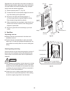
(3) To prevent possible hazard due to insulation failure,
the unit must be grounded.
(4) Each wiring connection must be done tightly and in
accordance with the wiring system diagram. Wrong
wiring may cause the unit to misoperate or become
damaged.
(5) Do not allow wiring to touch the refrigerant tubing,
compressor, or any moving parts of the fan.
(6) Unauthorized changes in the internal wiring can be
very dangerous. The manufacturer will accept no
responsibility for any damage or misoperation that
occurs as a result of such unauthorized changes.
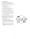
5-2. Recommended Wire Length and Diameter
Regulations on wiring diameter differ from locality to locality.
For field wiring requirements, please refer to your local elec-
trical codes. Carefully observe these regulations when car-
rying out the installation.
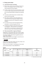
Table 6 shows maximum wire lengths for control line and
power line and fuse or circuit capacity.
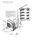
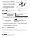
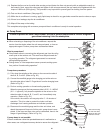
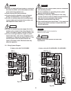
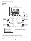
Refer to the wiring system diagram (Fig. 25a or 25b) for the
meaning of (A), (B), and (C) in Table 6.
Refer to your local codes or in the absence of local codes
see the National Electric Code: ANSI/NFPA70.
NOTE
Table 6
AWG
Max. Power Line Length (ft.)
(A)
Max. Control Line Length (ft.)
(B) (C)
Fuse
or
Circuit Capacity
Model
(#12) (#14)
CU-3KS19NBU 85 (Max.) 82 (Max.) 15 A
CU-4KS24NBU 85 (Max.) 82 (Max.) 20 A
CU-4KS31NBU 85 (Max.) 100 (Max.) 20 A
# ... AWG (American Wire Gau
g
e)