


Optima 45 - 3 11
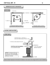
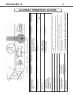
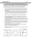
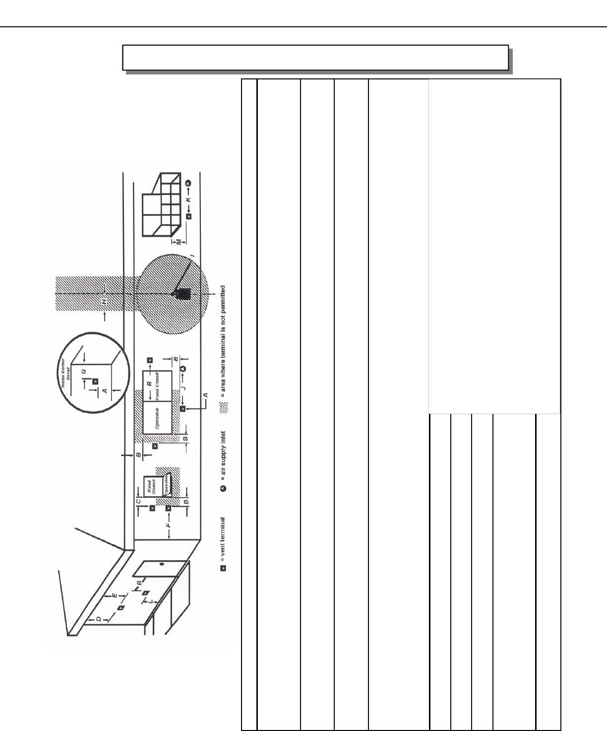
ALLOWABLE TERMINATION LOCATIONS
Canadian Installations (1) US Installations (2) Canadian Installations (1) US Installations (2)
A= Clearance above grade,
veranda, porch, deck, or
balcony
12 inches (30 cm) 12 inches (30 cm) J= Clearance to non-mechanical air
supply inlet to building or the
combustion air inlet o any other
appliance
12 inches (30 cm) 9 inches (23 cm)
B= Clearance to window or
door that may be opened
12 inches (30 cm) 12 inches (30 cm) K= Clearance to a mechanical
air supply inlet
6 feet (1.83 m) 3 feet (91 cm) above if
within 10 feet (3 m) hori-
zontally
C= Clearance to permanently
closed window
* * L= Clearance above paved
sidewalk or paved driveway
located on public property
7 feet (2.13 m) + *
D= Vertical clearance to
ventilated soffit located
above the terminal within a
horizontal distance of 2 feet
(61 cm) from the center line
of the terminal
* * M= Clearance under veranda,
porch, deck, or balcony
12 inches (30 cm) ++ *
E= Clearance to unventilated soffit * *
F= Clearance to outside corner * *
G= Clearance to inside corner * *
H= Clearance to each side of
center line extended above
meter/regulator assembly
3 feet (91 cm) within a
height 15 feet (4.5 m)
above the
meter/regulator assembly
*
L= Clearance to service
regulator vent outlet
3 feet (91 cm) *
(1) In accordance with the current CSA B149.1, National Gas and Propane Installation
Code
(2) In accordance with the current ANSI Z223.1/NFPA 54, National Fuel Gas Code
(+) A vent shall not terminate directly above a side walk or paved driveway that is located
between two single family dwellings and serves both dwellings
(++) Permitted only if veranda, porch, deck, or balcony is fully open on a minimum of two
sides beneath the floor.
(*) For clearances not specified in ANSI Z223.1/NFPA 54 or CSA B149.1, “Clearances shall
be in accordance with local installation codes and the requirements of the gas supplier.”