


·
DO NOT mount humidifiers in an area where
freezing may occur.
·
If humidifiers are mounted on a roof, a properly
ventilated, temperature controlled, (above
freezing), weatherproof enclosure must be used.
·
DO NOT mount humidifiers on vibrating surface.
Consult factory.
·
The humidifier shall not be installed directly on
carpeting, tile or other combustible material other
than wood flooring.
·
Some insulating materials may be combustible.
Prior to installing this appliance examine the area
for insulating material. If this appliance is
installed in an insulated space, it must be kept
free and clear of insulating materials. If insulation
is added after the appliance is installed, it will be
necessary to examine the area again.
GAS PIPING
Installation of piping must be in accordance with
local codes, and ANSI Z233.1, “National Fuel Gas
Code,” in the United States or CAN/CGA-B149
Installation Codes in Canada.
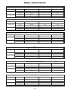
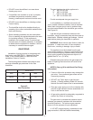
The following table indicates the maximum and
minimum allowable gas pressures for the Gas
Humidifier.
The gas inlet pipe size to the appliance is:
½” NPT for GS 100
¾” NPT for GS 200
1” NPT for GS 300 / 400
1 ¼” NPT for GS 500 / 600
Provide an adequate size gas supply line.
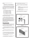
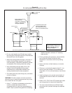
In all installations, a certified manual shut off
valve, located outside the cabinet, must be installed.
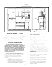
When black iron gas pipe is used, a sediment trap
must be located ahead of the humidifier gas controls.
See Figure #3.
Leak test all gas connections external to the
humidifier, using a commercial soap solution made to
detect leaks. Bubbles indicate gas leakage. Seal all
leaks before placing the humidifier in operation.
WARNING: Never use an open flame to check for
gas leaks. If a leak does exist, a fire or explosion
could occur, resulting in damage, injury or death.
The appliance must be isolated from the gas
supply piping system by closing its individual manual
shut-off valve during any pressure testing of the gas
supply piping system at test pressures equal to or
greater than 14” w.c. (3.5 kPa).
Dissipate test pressure from the gas supply line
before re-opening the manual shut off valve to the
appliance.
NOTES: (See pg 19 for additional Gas Piping
information)
·
Failure to follow this procedure may damage the
gas valve. Over pressured gas valves are not
covered by warranty.
·
DO NOT use Teflon tape on gas line pipe
threads. A flexible sealant suitable for use with
Natural Gas and Propane Gas is recommended.
·
Plan gas supply piping so it will not interfere with
removal of gas valves or blower assemblies and
front or side service doors.
·
All gas piping should be adequately supported to
prevent any strain on inlet piping.
The gas valve is provided with pressure taps to
measure gas pressure upstream and downstream,
(manifold pressure). The minimum gas pressure
shown is for the purpose of input adjustment.
A 1/8" NPT plugged tapping, accessible for test
gage connection, must be installed immediately
-5-
INCHES W.C.
GAS MIN. MAX.
Natural 4.5 9.0
Propane 9.0 13.0
Shut-off Gas Valve
(by others)
Sediment Trap
(by others)
Inlet coupling supplied
Union
(by others)
Figure #3
Gas Connection