


The vent terminal must be installed in the same
atmospheric pressure zone as the combustion air inlet
of the humidifier. If this is not possible (as in cases of
positive or negative room pressures) the humidifier
should be installed with the direct vent option.
ELECTRICAL
PRIMARY WIRING
All work concerning the electrical installation
must be performed by qualified personnel.
WARNING: The electrical parts inside the
humidifier are very sensitive to electrostatic discharge.
Appropriate measures against electrostatic discharge
(ESD protection) must be taken when carrying out
installation work.
·
The humidifier should only be connected to
primary power (mains power) after all installation
work has been completed.
· An external disconnect switch must be installed
close to the unit to allow for power interruption
during servicing and/or maintenance.
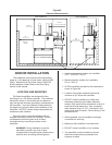
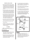
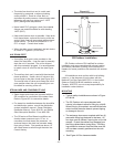
· Humidifiers require field wiring to primary voltage
terminal blocks. Power requirement must be
120V or 208-240 Vac, 15A separately fused
circuit, single phase. Use only copper wire with a
minimum 70 °C (158 °F) temperature rating.
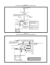
Wiring can be fed through a 7/8" hole on the
bottom or the top of the control compartment.
See Figure #1.
·
When installed, the appliance must be electrically
grounded in accordance with local codes or, in
the absence of local codes, with the National
Electrical Code, ANSI/NFPA 70, and/or the CSA
C22.1 Electrical Code, if an external electrical
source is utilized.
·
External wiring sizes must be in accordance with
NEC and/or CEC and existing local electrical
codes and by-laws.
LOW VOLTAGE CONTROL WIRING
All GS models require at least one type of input
control signal for unit operation. Refer to the sections
below that detail the types of controls that can be used
with each model.
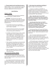
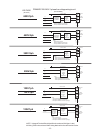
Low voltage control terminal strips are provided in
the electrical compartment. Internal sides are factory
wired. External sides are to be field wired. Refer to
the specific control-wiring diagram supplied with each
unit.
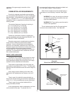
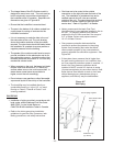
Field wiring from humidistat to humidifier and
between devices should be shielded 18 AWG or
heavier and kept as short as possible.
Controls are available from NORTEC as
accessories and can be ordered with the humidifier.
Controls by others may also be used as long as they
meet the criteria noted below. The following is a
summary of the common types of controls that may be
used with NORTEC Gas Humidifiers.
Wall or Duct Mounted Control On/Off
Humidistat: Wired to make on drop in humidity,
break on rise to setpoint. Set to desired RH. Can
be a make/break set of contacts from a Building
Automation System.
Duct Mounted Safety High Limit On/Off
Humidistat: Wired to make on drop in humidity,
break on rise to safety setpoint. Set to
approximately 85% RH as a safety to prevent
saturation and wetting in the duct. Highly
recommended for ducted applications.
Duct Mounted Safety Air Proving On/Off Switch:
Wired to make when sensing air flow, break when no
air flow. Used as a safety to prevent saturation when
there is no air flow. Highly recommended for ducted
applications.
Wall or Duct Mounted Modulating Humidistat:
Provides a modulating signal to the unit that
represents the output (up to 100%) required from the
humidifier. Signal type can be changed in the field via
dip switch settings on the logic control board.
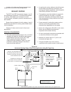
All GS models may be configured for either single
or dual channel modulation. Control signals can be
0-10 VDC or 0-20 mA (0-5 VDC, 1-5 VDC, 4-20 mA
and 2-10 VDC are also available). The unit must be
ordered from the factory for the desired signal type
and number of channels. When configured for
2-channel modulation the humidifier will generate
steam only if both channels indicate a demand. If both
channels are demanding steam the humidifier will
satisfy the lower demand signal.
-12-