


·
This appliance should not be connected to a
chimney flue servicing a separate appliance
designed to burn solid fuel. Never connect this
humidifier to a chimney servicing a fireplace.
·
This venting category cannot be used in direct
vent applications.
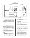
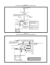
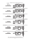
Installation as a Category III Appliance
·
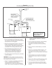
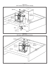
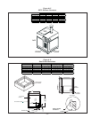
This venting system can be installed horizontally
or vertically and can terminate on a rooftop or
sidewall provided the NFGC (Nation Fuel Gas
Code) and CAN/CGA- B149 codes are followed.
The venting manufacturer instructions must also
be followed. See Figure # 6,#7 & #8.
·
This venting must be used in all direct vent
applications.
·
This category installation may not be common
vented with any other natural draft gas appliance
or power assist appliance. The humidifier cannot
share a chimney flue servicing an appliance
designed to burn solid fuel.
· Venting must be UL or UL/CSA listed, tested to
ULC-5636 Standard. Venting may be BH or L
vent. Special gas vent shall be listed and installed
in accordance with the terms of the special gas
vent listing and the manufacture’s instructions.
The special instructions listed below should be
followed as well.
·
All joints must be sealed using high temperature
RTV silicone.
BH Vent Manufacturers
1. Flex-L International
2. Fas-N Seal
3. Heat-Fab Inc.
4. Z Flex
·
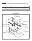
The gas humidifier is supplied with the following
exhaust outlets.
GS 100 3”
GS 200 4”
GS 300/400 5”
GS 500/600 6”
·
The venting must remain the same diameter
throughout the installation.
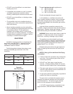
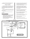
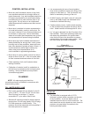
WARNING: Provide a screen or barrier to prevent
personal injury in areas where inadvertent personnel
contact with vent pipe can occur.
·
A minimum equivalent vent length of 7 feet must
be connected to the humidifier. Vent lengths
must not exceed 100’ (30 m). Each 90° elbow
is equivalent to 10’ and each 45° elbow equals 5'.
The vent run should be as direct as possible with
no more than 6 elbows in the system.
·
Diret vent applications, length of vent should not
exceed 70” in equivalent length.
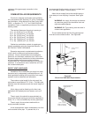
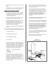
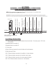
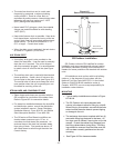
ADDITIONAL REQUIREMENTS WHEN VENTING
THROUGH A SIDEWALL
For sidewall venting, locate the humidifier as close
as possible to the wall being used.
Locate the vent terminal at least three feet above
any forced air inlet located within ten feet; or at least
four feet below, four feet horizontally from, or one foot
above any door, window, or gravity air inlet into any
building.
A minimum horizontal clearance of four feet from
electric meters, gas meters, regulator and relief
equipment is required.
For sidewall vent terminations, the humidifier must
be installed with the certified vent terminal that can be
purchased from Nortec.
GS 100 3” Nortec P/N 1502321
GS 200 4” Nortec P/N 1502322
GS 300/400 5” Nortec P/N 1507320
GS 500/600 6” Nortec P/N 1507321
Locate the vent terminal at least seven feet above
grade when it is adjacent to public walkways.
Locate the bottom of the vent terminal at least
twelve inches above grade or ground, or normally
expected snow accumulation level. The snow level
may be higher on walls exposed to prevailing winds.
Avoid areas where local experience indicates that
condensate drip may cause problems such as above
planters, patios, or over public walkways, or over an
area where condensate or vapor could create a
nuisance or hazard, or could be detrimental to the
operation of regulators, relief valves, or other
equipment. Refer to the vent manufacturer's
installation instructions.
-11-