


upstream of the gas supply connection to the
appliance.
COMBUSTION AIR REQUIREMENTS
Provide for adequate combustion and ventilation
air in accordance with Sections 8.3, Air for Combustion
and Ventilation, of the National Fuel Gas Code, ANSI
Z223.1, or Sections 7.2, 7.3, 7.4 of CAN/CGA B149
Installation Codes, or applicable provisions of the local
building codes.
The required free area of supply air opening is:
13 in. sq. (8,387 mm
2
), for GS 100
23 in. sq. (14,839 mm
2
), for GS 200
35 in. Sq. (22,581 mm
2
), for GS 300
47 in. Sq. (30,323 mm
2
), for GS 400
59 in. Sq. (38,064 mm
2
), for GS 500
71 in. Sq. ( 45,806 mm
2
), for GS 600
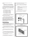
Cabinet top and bottom contain air openings to
provide combustion air to the forced draft blower. DO
NOT BLOCK THESE OPENINGS.
Excessive exposure to contaminated combustion
air will result in safety and performance related
problems. Known contaminates include halogens,
ammonia, and chlorides, excessive dust, lime or dirt.
Excessive exposure of electronics to the contaminants
will also result in performance related problems.
Contact NORTEC Technical Services if you have any
questions. If contaminants exist, isolate the unit from
the contaminated space.
DIRECT VENT GUIDELINES
Installation of the combustion air supply line must
be carried out by adequately qualified personnel. All
local regulations relating to the provision of air supply
systems must be observed and adhered to.
The maximum pipe length for the air supply line
and exhaust is equivalent to 70’ (21m). The vent pipe
diameter must be maintained over the overall length of
the vent.
All air piping must be listed type for direct vent
application with sealed joints and seams, such as Z
flex.
The air supply line should be approximately as
long as the flue gas venting and must be supported at
every 5 ft. (1.5 m) and additionally at every pipe bend.
The air supply line must be installed with air
supply terminals provided.
At low temperatures, water condensation can form
on the outside of the pipe. To prevent this, it is
recommended that the supply air line is insulated and
an in line heat is added. Consult factory.
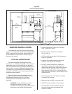
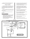
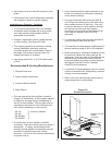
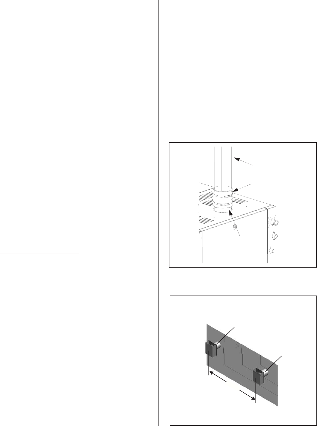
Attach the air supply line to the manifold using a
hose clamp or hose coupling if required. See Figure
#4.
WARNING: Air supply line should not obstruct
any services going to the humidifier front and
right side cabinet panels.
WARNING: BH Type venting must be used in
a direct vent application.
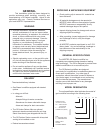
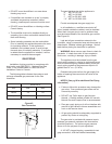
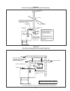
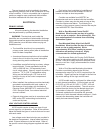
The air intake terminal and the flue gas terminal
must end at an outside location. See Figure #5.
-6-
Air Piping Insulated
(by others)
Hose Coupling
(by others)
Air Intake Connection
4ft-6ft
(1.2 m - 1.83 m)
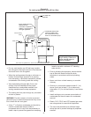
Exhaust terminal with
opening vertical.
Intake terminal with
opening vertical.
Keep 6“ (15.2 cm)
away from sidewall.
Figure #5
Direct Vent Side Wall Requirements