18
5. Open the furnace door and connect the oil line
to the intake port on the pump. Tighten other
port plugs on the pump. NOTE: Verify the oil
line is airtight! Air leaks can cause the pump
to lose prime and will create other problems
such as nozzle failure, odors, rumbling noise,
and false safety shutdown.
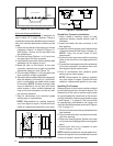
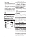
6. Insert the short length of the copper tube level
with the bottom of the duplex bushing. Form
the tube into an inverted “U” to serve as a vent.
Leak Check
To eliminate problems caused by air in the oil
line, all connections in the oil supply line and
all plugs, nuts, and fi ttings on the pump must
be airtight. NOTE: This includes the nut that
covers the pressure adjustment. It is important
that the hook-up be done carefully and with a
good fl aring tool.
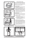
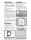
Prepare the burner for priming by attaching a
clear plastic hose over the bleed port fi tting and
fully opening the pump bleed port. Use a suitable
container to collect purged oil.
To ensure continuous operation, use a wire to
jump terminals T-T (or F-F) on the primary control
while burner is running.
After the piping to the furnace is complete, all
connections must be tested for leakage. This
includes pipe connections at the main gas valve,
emergency shutoff valve and each joint or union.
The soap and water solution can be applied using
a small paintbrush. If any bubbling is observed,
the connection is not sealed adequately and must
be retightened. Repeat the tightening and soap
check process until bubbling ceases.
Priming furnaces equipped with Honeywell
R7184 primary control:
1. While the ignition is on, press for 1/2 second
(or less), and release the reset button. The
lockout time will be extended to 4 minutes.
2. If prime is not established within the 4 minutes,
the control will lock out. Press the reset button
to reset the control.
3. Repeat steps 1 & 2 (if needed) until the oil
pump is fully primed.
Priming furnaces equipped with the Beckett
7505 primary control:
1. After the burner starts, press and hold the
reset button until the yellow LED turns on (15
seconds). This indicates that the button has
been held long enough.
2. Release the reset button. The yellow LED will
turn off and the burner will start up again.
3. At burner start up, click the reset button while
the igniter is still on. This transitions the control
to a dedicated pump prime mode, during
which the motor, igniter and valve are powered
for 4 minutes. The yellow LED will be on.
NOTE: If prime is not established during the
four minute pump prime mode, repeat step 3
until the oil pump is fully primed.
4. When oil fl ow is clear and free of air bubbles,
close air-bleed valve and tighten. (Time to
bleed air out will vary depending on length of
oil line, number of bends, etc.)
Fuel Oil Type
Do not use fuel oil heavier than Grade No. 2.
Grade No. 1 may be used where the oil supply
is subject to low temperatures.
DO NOT USE GASOLINE, CRANKCASE OIL,
OR ANY OIL CONTAINING GASOLINE.
WARNING:
Failure to keep supply of oil clean
by various procedures described
above may cause failure of certain
components such as the fuel pump
gears, check valve, shaft seal, or
burner nozzle which may result in
a burner fi re.
Conversion to Propane (LP) Gas
This gas fi red heating appliance was shipped from
the factory for use with natural gas. However, the
appliance can be converted for use with LP gas.
Use the following procedure for gas conversion
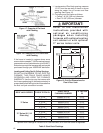
of the burner. See Table
Atmospheric and Direct Ignition Furnaces
1. Follow the instructions “How to Shut Off Gas”
on pages 21 or 22.
2. Disconnect the gas pipe union and the electrical
wires connected to the gas valve.
3. Remove the pilot tube and thermocouple from
the gas valve (M1G).
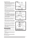
4. Remove the gas valve assembly:
a. Remove screw(s) from gas valve bracket.
Gas valve and spud may be removed.
Orifi ce is located at the end of the spud
(M1G or M1M) or remove three (3) bolts
from U-shaped manifold plate and orifi ce
assembly (M1B).
5. Replace the main orifi ce with the L.P. gas
orifi ce supplied in the envelope located by the
gas valve. Verify the orifi ce size matches the
nameplate or Table 10 (page 31). NOTE: It is
not necessary to convert the pilot orifi ce.


