


19
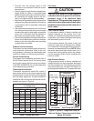
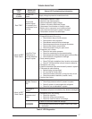
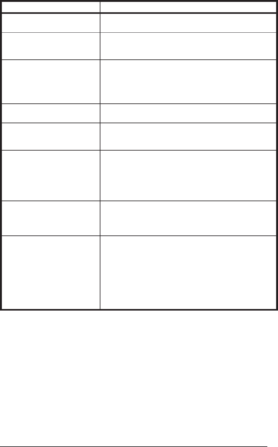
Table 5. Module Wiring Troubleshooting
Miswired Module Indication Recommended Troubleshooting Action
Green LED is not on, module
does not power up
• Determine if both R & C module terminals are connected.
• Verify voltage is present at module’s R & C terminals.
Green LED intermittent,
module powers up only when
compressor runs
• Determine if R & Y terminals are wired in reverse.
• Verify modules R and C terminals have a constant source.
Trip LED is on, but system and
compressor check OK
• Verify Y terminal is connected to 24VAC at contactor coil.
• Verify voltage at contactor coil falls below 0.5VAC when
off.
• Verify 24VAC is present across Y & C when thermostat
demand signal is present. If not, R & C are reversed wired.
TRIP LED and ALERT LED
fl ashing together
• Verify R and C terminals are supplied with 19 - 28VAC.
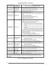
ALERT Flash CODE 3 displayed
incorrectly (Compressor short
cycling)
• Verify Y terminal is connected to 24VAC at contactor coil.
• Verify voltage at contactor coil falls below 0.5VAC when
off.
ALERT Flash Code 5, 6, or 7
displayed incorrectly (Open
Circuit, Open Start Circuit or
Open Run Circuit)
• Verify the compressor run and start wires are routed
through the module’s current sensing holes.
• Verify the Y terminal is connected to 24VAC at contactor
coil.
• Verify voltage at contactor coil falls below 0.5VAC when
off.
ALERT Flash Code 6 (Open
Start Circuit) displayed for
Code 7 (Open Run Circuit) or
vice-versa
• Verify the compressor run and start wires are routed
through the correct module sensing holes.
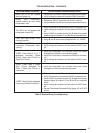
ALERT Flash Code 8 displayed
incorrectly (Welded Contactor)
• Determine if module’s Y terminal is connected.
• Verify Y terminal is connected to 24VAC at contactor coil.
• Verify 24VAC is present across Y & C when thermostat
demand signal is present. If not, R and C are reversed
wired.
• Verify voltage at contactor coil falls below 0.5VAC when
off.
• Review Thermostat Demand Wiring (page 10) for Y & C
wiring.
TROUBLESHOOTING - CONTINUED