


10
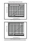
again after the discharge pressure decreases to
460 psig. NOTE: When the switch opens and
then closes, there will be a 3 minute short cycling
delay before the outdoor unit will energize. Under
normal conditions the switch is closed.
Comfort Alert
TM
Diagnostics Module
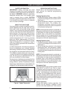
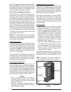
The Comfort Alert
TM
Diagnostics Module is a
breakthrough innovation for troubleshooting
heat pump and air conditioning system failures.
The module installs easily in the electrical box of
the outdoor unit near the compressor contactor.
By monitoring and analyzing data from the
Copeland scroll compressor and the thermostat
demand, the module can accurately detect the
cause of electrical and system related failures
without any sensors. A fl ashing LED indicator
communicates the ALERT code and a diagnostic
key is also imprinted on the side of the module
to quickly direct the technician to the root cause
of a problem. See Figure 3.
NOTE: This module does not provide safety
protection! The Comfort Alert
TM
Diagnostics
Module is a monitoring device and cannot control
or shut down other devices.
24 VAC Power Wiring
The Comfort Alert
TM
module requires a constant
nominal 24 VAC power supply. The module cannot
be powered by the C terminal on a defrost board
or other control board without experiencing
nuisance alerts. NOTE: The wiring to the module’s
R & C terminals must be routed directly from the
indoor unit or thermostat.
If the constant 24 VAC (R wire) is not present in
the outdoor unit, use one of the spare wires in the
thermostat cable to bring power to the module.
Connect the other end of the spare wire to R at
the indoor unit or thermostat.
Thermostat Demand Wiring
The Comfort Alert
TM
module requires a
thermostat demand signal to operate properly.
The thermostat demand signal input (labeled Y
on the module), should always be connected to
the compressor contactor coil. NOTE: When the
coil is energized, the demand signal input is 24
VAC. When the coil is not energized, the demand
signal input should be less than 0.5 VAC.
NOTES:
• Factory installed modules have different
thermostat demand signal wiring. Always
follow manufacturer wiring instructions when
replacing the module.
• After the thermostat demand signal is
connected, verify that 24 VAC across Y & C
when demand is present.
Interpreting the Diagnostic LED’s
When an abnormal system condition occurs, the
Comfort Alert
TM
module displays the appropriate
ALERT and/or TRIP LED will fl ash a number of
times consecutively, pause and then repeat the
process. To identify a Flash Code number, count
the number of consecutive fl ashes.
Each time the module powers up, the last ALERT
Flash Code that occurred prior to shut down
is displayed for one minute. The module will
continue to display the LED until the condition
returns to normal or if 24 VAC power is removed
from the module.
LED Description
• POWER LED (Green): indicates voltage is
present at the power connection of the module.
• ALERT LED (Yellow): communicates an
abnormal system condition through a unique
fl ash code. NOTE: The ALERT LED will fl ash
consecutively, pause and then repeat the
process. The number of consecutive fl ashes,
referred to as the Flash Code, correlates to
a particular abnormal condition. Detailed
descriptions of these ALERT Flash Codes
are listed in Table 4 (page 14).
• TRIP LED (Red): indicates a demand signal
is received from the thermostat, but current
to the compressor is not detected by the
module. The TRIP LED typically indicates
if the compressor protector is open or the
compressor has no power.
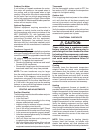
The scroll compressor’s R (run), C (common),
and S (start) wires are routed through the holes in
the Comfort Alert
TM
module marked R, C, and S.
NOTE: The common wire does not need to be
routed through the module for it to operate.
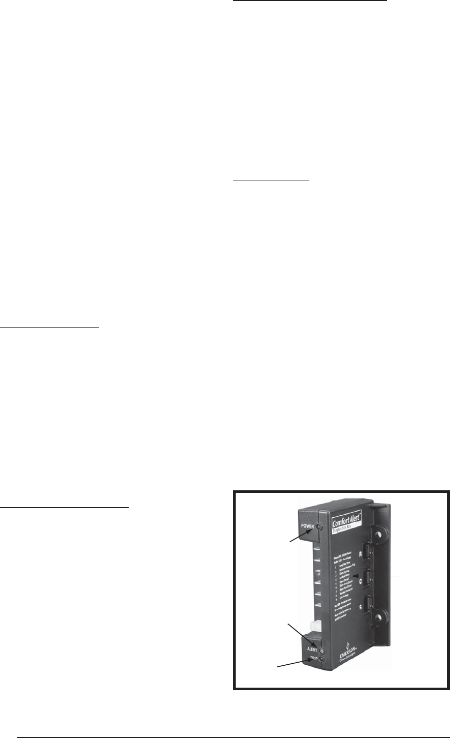
Figure 3. Comfort Alert
TM
Diagnostics
Module
POWER LED
(Green)
TRIP LED
(Red)
ALERT LED
(Yellow)
Diagnostic
s
Key