WS-415-71 / 09.07.00
5
CARE OF GLASS AND PLATED
PARTS
If the glass is not kept clean permanent discolouration
and / or blemishes may result. Normally a hot fire will clean
the glass. The most common reasons for dirty glass in-
clude: not using sufficient fuel to get the stove thoroughly
hot, using green or wet wood, closing the draft so far that
there is insufficient air for complete combustion. If it is
necessary to clean the glass, use a soft cloth with a non-
abrasive cleaner. DO NOT CLEAN THE GLASS WHEN HOT!
The glass is very strong but do not let burning fuel rest or
fall against it and always close the door gently. NEVER
FORCE IT SHUT! If the glass should ever crack while the
fire is burning, do not open the door until the fire is out and
do not operate the stove again until the glass has been
replaced with a new 5mm thick piece of ceramic glass,
available from your Napoleon / Wolf Steel Ltd. dealer.
DO NOT SUBSTITUTE MATERIALS. To remove the door,
open and lift out; remove the screws and brackets holding
the glass in place. Remove all broken glass. Wrap the
edges of the new glass with a U-shaped strip of fiberglass
gasket, covering 1/4" on each side. Place this gasketed
glass in position and replace the brackets and screws.
When finished, you should be able to move the glass
slightly, horizontally and vertically.
Do not use abrasive cleaners to clean plated parts. Buff
lightly with a clean dry cloth.
Prolonged high temperature burning with the door ajar may
cause a permanent rainbowing effect on the lower edge of
a gold plated door.
HI-EFFICIENCY
HEATING
FOUR OPTIONS
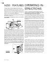
For a basic hi-efficiency fireplace, blowers are not needed,
however, they are recommended for extra heat output and
efficient air circulation. This can be especially important if the
fireplace is to be used as a major source of heat. Without the
use of blowers, the Napoleon Model NZ25 will operate as a
regular hi-efficiency fireplace.
A BLOWER KIT (NZ62) may be purchased with the
option of adding up to one additional blower. These blowers
are installed in the rear of the unit and are used to direct the
heat into the room where the fireplace is located. The blow-
ers are controlled, by a variable speed switch, located inside
the fireplace.
A THERMOSTATIC AIR CONTROL (NZ690KT), may
be used for constant heat, complete with automatic damper
and thermostat, wall mounted in the room containing the
fireplace, and at least 10 feet (minimum) from the fire-
place. This option allows your room temperature to be
kept as evenly controlled as it would with other fuels while
still enjoying the comfort of wood heat.
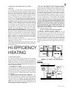
THE HOT AIR GRAVITY VENT SYSTEM (NZ220)
may be used to distribute heat to an adjoining room (lo-
cated either above, or beside the room containing the fire-
place) by way of vents, eliminating the need of an addi-
tional blower. While this system may be used in conjunc-
tion with the optional blowers, it could reduce the flow of
hot air being distributed to additional rooms. It must be
experimented with and the dampers adjusted manually to
suit your requirements. This may take a few attempts;
thereafter adjustments should no longer be required as is
normally experienced with your central heating system
registers. The hot air vent must be installed in an up-
ward direction! NEVER install in a downward direction.
Figures 4c, 4d & 4e. The hot air gravity vent system is
not be connected to a central heating system (for this
application use the NZ62CH). No more than two hot air
gravity vents can be installed to fireplace. Individual vent
runs are not to exceed 10 feet.
All hot air gravity vents must be insulated.
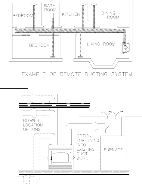
A CENTRAL HEATING SYSTEM (NZ62CH) may be
used to heat rooms up to 50 feet from the unit. A wall
mounted thermostat located in the room to be heated con-
trols the blower supplying warm air from the room con-
taining the fireplace. If a hot air duct system exists, the
central heat blower may safely be tied into this system to
reduce the amount of new ducting required. Consult with
a heating specialist to ensure a proper duct layout for your
home.
FIGURES 3


