


WS-415-71 / 09.07.00
11
OPTIONAL
BLOWER
INSTALL ATION
NSTALLATION TO BE DONE BY A QUALIFIED INSTALLER
and must be electrically connected and grounded in ac-
cordance with local codes. In the absence of local codes,
use the current CSA C22.1 CANADIAN ELECTRICAL
CODE.
1. Turn off any elec-
trical power to the fire-
place (if applicable).
Open the lower louvred
control door.
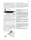
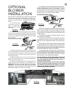
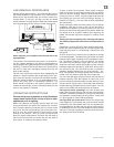
2. Locate the vibration reducing pad (one per blower)
over the two threaded studs, piercing 2 holes into the pad.
The blower must be able to be positioned entirely onto the
pad. If only one blower is used, install on the left hand side
of the fireplace.
ONE BLOWER INSTALLATION:
3. Slide the blower to the back of the fireplace taking
care not to damage the terminals. Position the blower onto
the studs and secure using the lock washers and wing
nuts provided. Pull the leads to the front and right side of
the ashpan housing.
4. Remove the junction box. Use a nut connector to
attach one of the black wires of the variable speed switch
to the black power supply wire.
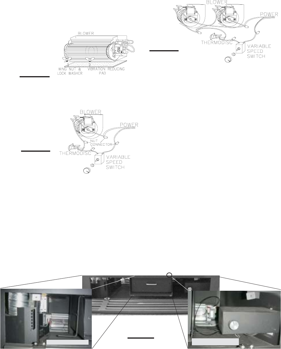
5. Pass the two blower leads and one thermodisc lead
through the junction box bushing. The thermodisc is lo-
cated inside the outer shell, just above the louvre door.
FIGURE 21. Connect one blower lead to the thermodisc
lead using a nut connector and the other blower lead to the
white power supply wire using a nut connector.
6. Thread the other thermodisc lead through the junc-
tion box bushing and connect to the other black wire of the
variable speed switch using a nut connector. Secure
ground wire (green) to the threaded weld stud located on
the junction box wall. Re-install the junction box. Ensure
that the wires will not interfere with the blower.
DUAL BLOWER INSTALLATION:
3. Slide the first blower to the back of the fireplace tak-
ing care not to damage the terminals. Position the blower
onto the studs and secure using the lock washers and wing
nuts provided. Pull the leads to the front and right side of the
ashpan housing.
4. Slide the second blower into place, position onto the
studs and secure as before.
5. Remove the junction box cover located on the lower
right outside of the unit. Use a nut connector to attach the
black wire of the variable speed switch to the black power
wire.
6. Pass the four blower leads and both thermodisc leads
through the junction box bushing. Connect one blower lead
from each blower and one of the thermodisc leads using a
nut connector and connect the other two blower leads to the
white power supply wire using a nut connector.
7. Connect the other thermodisc lead to the black wire
of the variable speed switch using a nut connector. Secure
ground wire (green) to the threaded weld stud located on
the junction box wall. Re-install the junction box. Ensure
that the wires will not interfere with the blower.
Because the blower is thermally activated, when turned
on, it will automatically start approximately 15-45 min-
utes after lighting the fireplace. Use of the blower in-
creases the output of heat.
Drywall dust will penetrate into the blower bearings
causing irreparable damage and must be prevented
from coming into contact with the blower or its com-
partment. Any damage resulting from this condition is
not covered by the warranty policy.
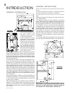
FIGURE 19
FIGURE 20b
FIGURE 21
white
black
black
white
JUNCTION BOX c/w
VARIABLE SPEED
SWITCH
X
THERMODISC LOCATION
SINGLE BLOWER
FIGURE 20a
SECOND BLOWER