


7
W415-0559 / 02.15.06
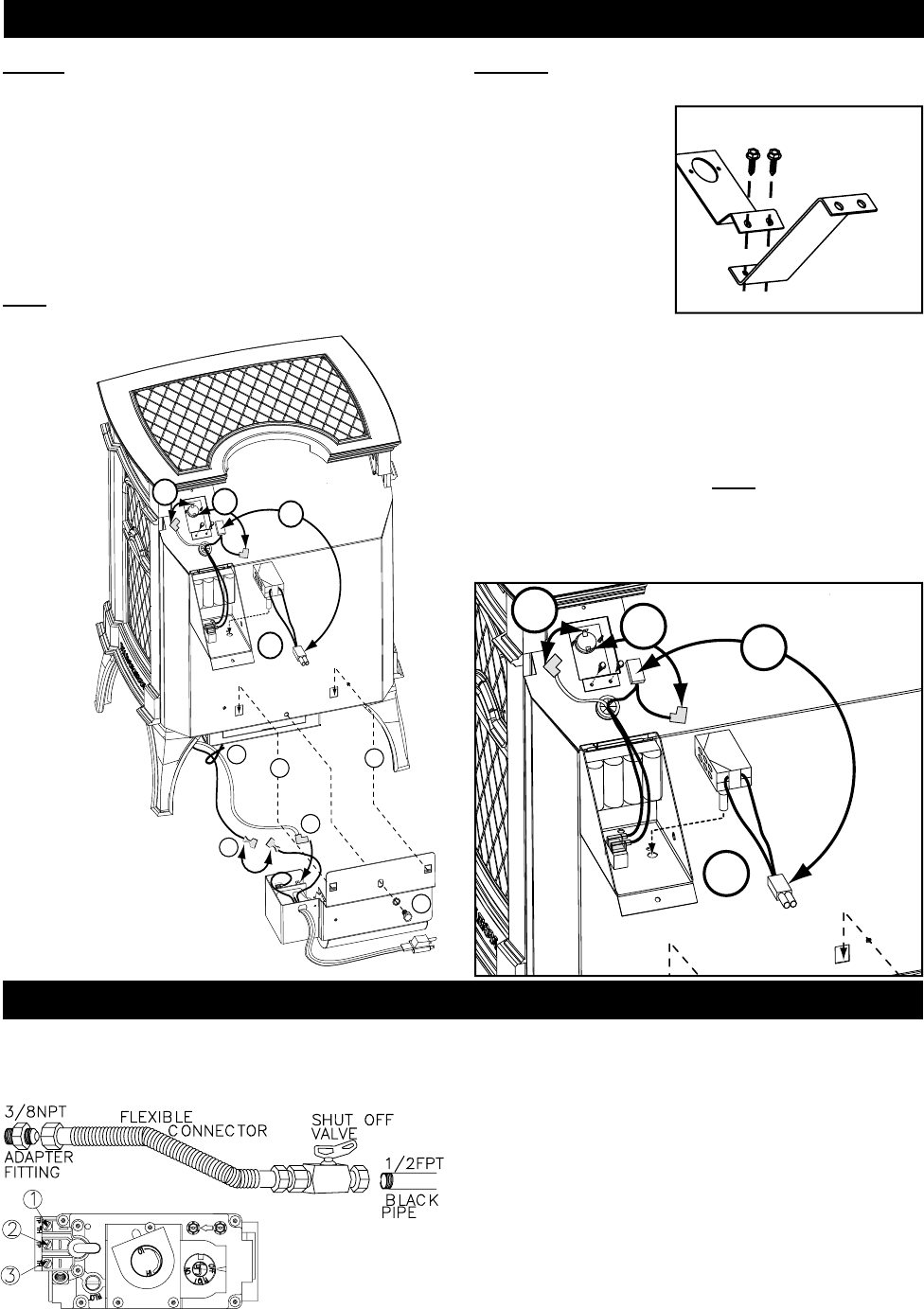
BLOWER INSTALLATION
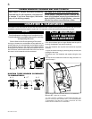
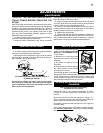
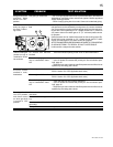
GAS INSTALLATION
1. Install rigid black pipe, or 1/2" type L copper tubing with a
shut-off valve to the stove.
2. Seal and tighten the gas line securely to a fl ex connector.
DO NOT KINK FLEXIBLE CONNECTOR.
3. Check for gas leaks by
brushing on a soap and
water solution. Do not use
open fl ame.
1/2FPT
3/8NPT
CONNECTOR
FITTING
ADAPTER
FLEXIBLE
PIPE
BLACK
VALVE
SHUT OFF
For ease of accessibility, an optional remote wall switch or
millivolt thermostat may be installed in a convenient loca-
tion. Route 2 strand solid core millivolt wire from the gas
stove to the wall switch / millivolt thermostat. The recom-
mended maximum lead length depends on the wire size:
wire size max. length
14gauge 100 feet
16gauge 60 feet
18gauge 40 feet
Disconnect the existing wires from terminals 1 and 3 (from
the on/off switch) and replace with the leads from the wall
switch/millivolt thermostat.
1
2
3
O
TH
TH
O
T
P
I
L
L
O
T
I
H
N
O
P
O
I
F
F
TP
TP
TH
TH
TP
TP
L
2
3
4
4
5
1
7
7
8
9
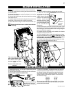
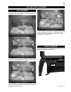
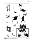
Blower (SEE LOCATION AND CLEARANCES IN INSTRUCTION MANUAL)
1. Cut and remove the tie securing the blower switch wires
to the heat shield.
2. Connect the white wire coming from below the unit to the
terminal on the blower.
3. Connect the black blower wire to the black wire coming
from below the unit.
4. Insert the clips on the blower housing into the cutouts in the
rear shield. Push down to lock the clips into position.
5. Secure the blower using the screw and lock washer sup-
plied.
Note: Ensure that all the wires are tucked into the blower
switch housing.
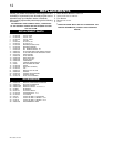
Switches
6. Open the switch housing by removing the top screw.
7. With the 2 screws
and extension bracket
supplied in the unit
baggie, fasten extension
bracket to the thermodisc
bracket. Install bracket
assembly as shown, using
2 of the screws supplied.
Connect the fl agged leads
to the terminals of the
thermodisc.
8. Remove the knock out from the switch housing label. Install
the variable speed switch (rheostat) into the housing with the
wires facing up. Secure the switch to the housing using the
pal nut and the knob supplied.
9. Connect the male connector on the switch to the female
connector coming from the unit.
10. Pilot Indicator Light: Install the batteries as shown.
Replace the batteries annually. Note: If replacing the pilot
indicator light , ensure that the red wire lead connects to
the red lead of the thermopile and black to white.
11. Tuck all of the wires into the switch housing and close.
Secure using the screw removed in step 6.
This unit comes equipped
with a pilot indicator light
that blinks every few
seconds when the pilot
is on.
For more information see
step #10.
THERMODISC
EXTENSION
BRACKET
THERMODISC
BRACKET
7
7
8
9