


13
W415-0536 / C / 09.06.06
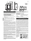
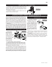
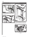
The vent system must be supported approximately every 3
feet for both vertical and horizontal runs. Use Wolf Steel vent
spacers or equivalent every 3 feet and either side of each
elbow to maintain the minimum 1¼” clearance between the
outer and inner vent pipes. Use Wolf Steel support ring as-
sembly or equivalent noncombustible strapping to maintain
the minimum clearance to combustibles for both vertical and
horizontal runs.
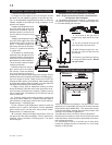
1. -
place into position.
Measure the vent
length required
between terminal
-
ing into account
the additional
length needed for
the finished wall
surface and any
1¼” overlaps between venting components.
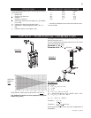
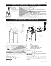
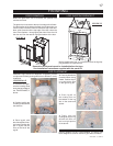
2. Apply high temperature sealant (W573-0007 not pro-
tapping screws. Repeat using 7” piping.
3.
top and the lettering in an upright, readable position) insert
the terminal into both vent pipes with a twisting motion to
ensure that both the terminal sleeves engage into the vent
pipes and sealant. Secure the terminal to the exterior wall and
make weather tight by sealing with caulking (not supplied).
1.
joint and screw holes using the high temperature sealant
(W573-0007 not provided).
2.
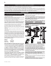
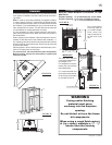
FIREPLACE vENT CONNECTION
USING RIGID vENT COMPONENTS
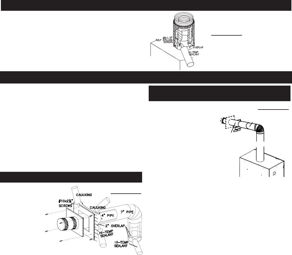
HORIzONTAL AIR TERMINAL INSTALLATION
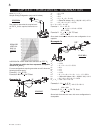
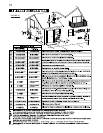
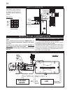
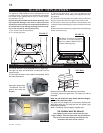
EXTENDED HORIzONTAL AIR TERMINAL
INSTALLATION
FIGURE 20
1. Follow the instructions
for “Horizontal Air Terminal
Installations”, items 1 to 3.
2. Continue adding com-
ponents alternating inner
and outer venting. Ensure
that all 4” venting and elbows
attached and each compo-
nent is securely fastened to
the one prior. Attach the 4”
telescopic sleeve to the vent
run.
Repeat using a 7” telescopic sleeve. Secure and seal as
before. To facilitate completion, attach 4” and 7” couplers to
the air terminal.
3. Install the air terminal. See item 3 of the Horizontal Air
-
nect to the air terminal assembly. Fasten with self tapping
screws and seal. Repeat using the 7” telescopic sleeve.
HI-TEMP
SEALANT
7" PIPE
2" OVERLAP
4" PIPE
CAULKING
SCREWS
#10x2½"
CAULKING
SEALANT
HI-TEMP
FIGURE 21
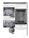
VENTING
TELESCOPIC SLEEVE
20"
COUPLER
AIR TERMINAL
FIGURE 22