


11
W415-0100 / D / 01.13.04
Where possible, cover the sides and top edges of the flash-
ing with roofing material.
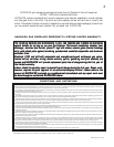
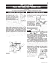
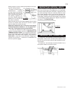
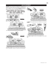
6. Apply a heavy bead of
weatherproof caulking
2 inches above the flashing.
Slide the storm collar around
the air terminal and down to
the caulking. Tighten to en-
sure that a weather-tight seal
between the air terminal and
the collar is achieved.
Attach the other storm collar centred between the air intake
and the air exhaust slots onto the air terminal. Tighten
securely. Attach the vertical rain cap.
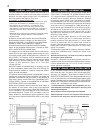
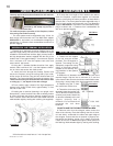
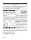
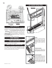
Spacers are attached to the 4" inner flex liner at prede-
termined intervals to maintain a 1-1/4" air gap to the 7"
outer liner. These spacers must not be removed.
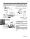
7. If more liner needs to be used to reach the fireplace,
follow the same procedure as found in HORIZONTAL AIR
TERMINAL INSTALLATION. The vent system must be sup-
ported approximately every 3 feet for both vertical and hori-
zontal runs. Use Wolf Steel support ring assembly
W010-0370 or equivalent noncombustible strapping to
maintain the minimum 1" clearance to combustibles as
well as to prevent sagging.
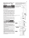
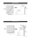
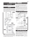
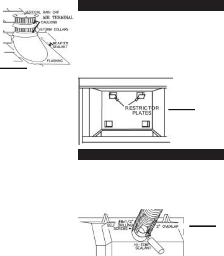
Vertical installations running longer than 10 feet may dis-
play a very active flame. If this appearance is not desirable,
remove the brick baffle from the firebox, exposing the flue
gas outlet openings. Bend the restrictor plates up (from
their normal opening of 45°) into the flue openings. Re-
place the brick baffle. This reduces the velocity of the ex-
haust gases, slowing down the flame pattern and creating
a more traditional gentle appearance. Specific instructions
are shown in "Trouble Shooting".
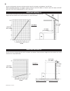
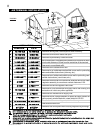
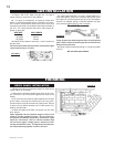
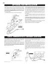
1. Install the 4 inch diameter aluminium flexible liner to
the fireplace. Secure with 3 screws and flat washers. Seal
the joint and screw holes using the high temperature seal-
ant provided.
2. Install the 7 inch diameter aluminium flexible liner to
the fireplace. Attach and seal the joints.
FIGURE 19
FIGURE 20
FIGURE 21
RESTRICTING VERTICAL VENTS
FIREPLACE VENT CONNECTION