


17
W415-0210 / E / 06.25.03
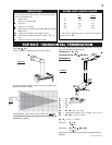
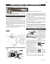
Use only approved aluminum flexible liner kits marked:
"Wolf Steel Approved Venting" as identified by the stamp only on the 7” outer liner.
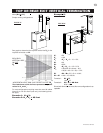
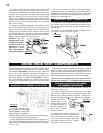
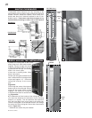
FIGURE 27
For safe and proper operation of the fireplace, follow
the venting instructions exactly.
1. Cut or frame a hole in an exterior wall with a minimum
round or square opening of 10½ inches. Secure the firestop
spacer over the opening to the interior wall.
2. Stretch the 4" diameter aluminum flexible liner to the
required length taking into account the additional length
needed for the finished wall surface. Slip the liner a mini-
mum of 2" over the inner sleeve of the air terminal and
secure with 3 #8 screws. Apply a heavy bead of the high
temperature sealant.
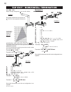
3. Using the 7" diameter flexible aluminum liner, slide
over the outer combustion air sleeve of the air terminal and
secure with 3 #8 screws. Seal as before.
The air terminal mounting plate may be recessed into
the exterior wall or siding by 1½", the depth of the return
flange.
4. Insert the liners through the firestop maintaining the
required clearance to combustibles. Holding the air termi-
nal (lettering in an upright, readable position), secure to
the exterior wall and make weather tight by sealing with
caulking (not supplied).
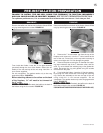
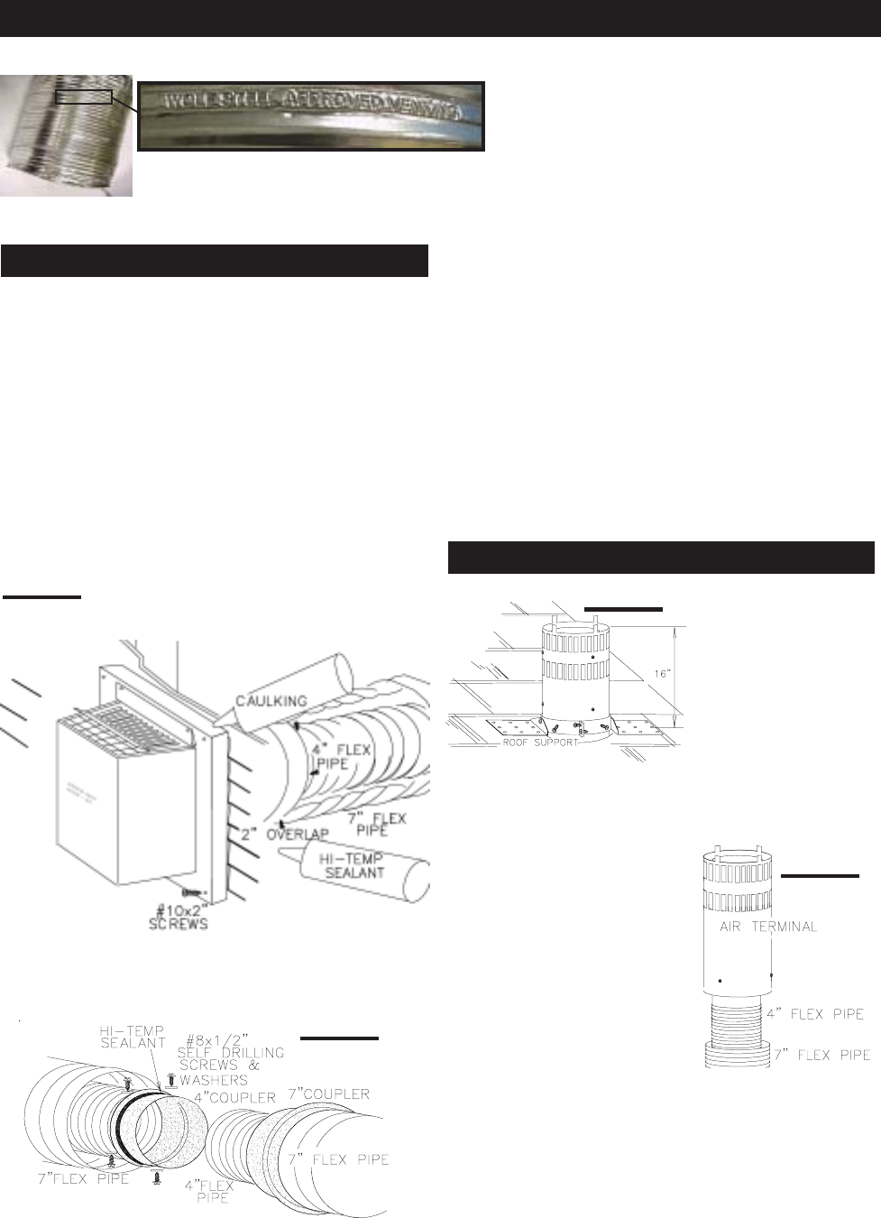
5. Apply a heavy bead of the high temperature sealant to
the inside of the 4" liner approximately 1" from the end. Slip
the liner a minimum of 2" over the fireplace vent collar and
secure with 3 #8 screws.
6. Using the 7" diameter flexible aluminium liner, apply
sealant, slide a minimum of 2" over the fireplace combus-
tion air collar and secure with 3 #8 screws.
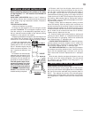
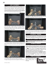
7. If more liner needs to be used to reach the fireplace,
couple them together as illustrated. The vent system must
be supported approximately every 3 feet for both vertical
and horizontal runs. Use noncombustible strapping to
maintain the minimum 1" clearance to combustibles.
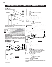
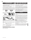
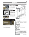
FIGURE 28
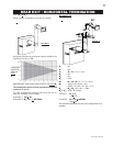
1. Fasten the roof sup-
port to the roof using the
screws provided. The
roof support is optional.
In this case the venting
is to be adequately sup-
ported using either an al-
ternate method suitable
to the authority having ju-
risdiction or the optional
roof support.
2. Stretch the 4" diameter aluminium flexible liner to the
required length. Slip the liner a minimum of 2" over the
inner sleeve of the air terminal
and secure with 3 #8 screws.
Seal using a heavy bead of the
high temperature sealant.
3. Repeat using 7" diameter
aluminium flexible liner.
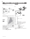
4. Thread the air terminal pipe
assembly down through the roof.
The air terminal must be located
vertically and plumb. Attach the
air terminal assembly to the roof
support, ensuring that a mini-
mum 16" of air terminal will penetrate the roof when fas-
tened.
DO NOT CLAMP THE FLEXIBLE ALUMINIUM LINER.
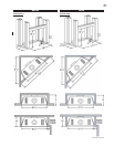
FIGURE 29
FIGURE 30
USING FLEXIBLE VENT COMPONENTS
HORIZONTAL AIR TERMINAL INSTALLATION
VERTICAL AIR TERMINAL INSTALLATION