


21
W415-0612 / C / 01.25.08
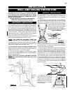
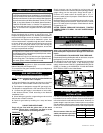
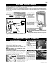
FIGURE 35
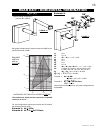
GAS INSTALLATION
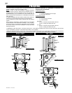
This Mobile/Manufactured Home Listed appliance comes
factory equipped with a means to secure the unit. The
fi replace is equipped with two 1/4" diameter holes located in
the front left and right corners of the base. For mobile home
installations, the fi replace must be fastened in place. Use
#10 hex head screws, inserted through the holes in the base
to secure. Always turn off the pilot and the fuel suuply at the
source, prior to moving the mobile home. After moving the
mobile home and prior to lighting the fi replace, ensure that
the logs are positioned correctly.
Conversion Kits
The mobile home appliance is fi eld convertible between
Natural Gas (NG) and Propane (LP).
To convert from one gas to another consult your Napoleon®
dealer/distributor.
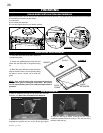
MOBILE HOME INSTALLATION
Proceed once the vent installation is complete.
NOTE: All gas connections must be contained within the
fi replace when complete.
1. Move the fi replace into position and secure to the fl oor
through the 1/4" holes located at either side of the base.
2. The fi replace is designed to accept 3/8" gas supply line.
The fi replace is equipped with a 3/8" manual shut-off valve.
3. Connect the gas supply in accordance to local codes.
In the absence thereof, install according to the National
Installation Code.
4. When fl exing any gas line, support the gas valve so that
the lines are not bent or kinked.
5. Check for gas leaks by brushing on a soap and water
solution.
DO NOT USE OPEN FLAME.
Purge all gas lines with the glass door of the stove
removed. Assure that a continuous gas fl ow is at the
burner before re-installing the door.
This appliance is certifi ed to be installed as an OEM (Origi-
nal Equipment Manufacturer) installation in a manufactured
home or mobile home and must be installed in accordance
with the manufacturer’s instructions and the Manufactured
Home Construction and Safety Standard, Title 24 CFR, Part
3280, in the United States or the Mobile Home Standard,
CAN/CSA Z240 MH Series, in Canada. This appliance is
only for use with the type(s) of gas indicated on the rating
plate. A conversion kit is supplied with the mobile home
appliance.
This appliance is certifi ed to be installed in an aftermarket
permanently located, manufactured (mobile) home, where
not prohibited by local codes.
This fi replace is only for use with the type of gas indicated
on the rating plate. This fi replace is not convertible for use
with other gases, unless a certifi ed kit is used.
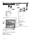
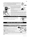
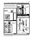
For ease of accessibility, an optional remote wall switch may
be installed in a convenient location. Connect a 20ft length of
millivolt wire from the wall switch to the module. However, if a
greater length is required route 2-strand (solid core) millivolt
wire through the electrical hole located at the bottom left side
of the unit. The recommended maximum lead length depends
on wire size:
Do not connect either the wall
switch, thermostat or gas valve
directly to 120 volt electricity.
OPTIONAL WALL SWITCH
INSTALLATION
WIRE SIZE LENGTH
14 Gauge 100 Feet
16 Gauge 60 Feet
18 Gauge 40 Feet
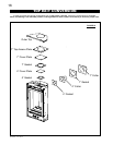
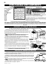
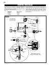
ELECTRICAL INSTALLATION
L1
L2
CABLE
CONNECTOR
ELECTRICAL
BOX COVER
(C/W GROUND SCREW)
SWITCH HOUSING
(C/W 2 RECEPTACLES)
WIRE NUTS
Do NOT use the fi replace if any part has been under
water. Call a qualifi ed service technician IMMEDIATELY to
have the fi replace inspected for damage to the electrical
circuit.
IT IS NECESSARY TO HARD WIRE THIS FIREPLACE.
Permanently framing the fi replace with an enclosure, requires
the fi replace junction box to be hardwired.
This fi replace must be electrically connected and grounded
in accordance with local codes. In the absence of local
codes, use the current CSA C22.1 CANADIAN ELECTRICAL
CODE in Canada or the ANSI/NFPA 70-1996 NATIONAL
ELECTRICAL CODE in the United States.
RISK OF ELECTRIC SHOCK!
Control operates with 120 volt electricity.
!
WARNING
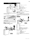
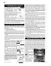
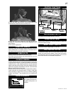
Shown
in “OFF”
position.
Manual
Shut-off Valve
A
B
Supply pressure can be checked by turning screw (A)
counter-clockwise until loosened and then placing pressure
gauge tubing over the test point. Gauge should read 7”
(minimum 4.5”) water column for natural gas or 13” (11”
minimum) water column for propane. Check that main burner
is operating on “HI”.
Manifold pressure can be checked the same as above using
screw (B). Gauge should read 3.5” water column for natural
gas or 10” water column for propane. Check that main burner
is operating on “HI”.
AFTER TAKING PRESSURE READINGS, TIGHTEN
SCREWS FIRMLY TO SEAL. DO NOT OVERTORQUE.
LEAK TEST