


20
W415-0612 / C / 01.25.08
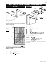
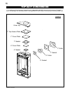
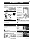
REAR VENT APPLICATION: Attach 4" and 7" elbows to
the fi replace. Secure with 3 screws and seal the joints and
screw heads using high temperature sealant. Proceed to
step 1 below.
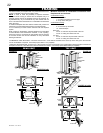
TOP VENT APPLICATION:
1. Move the fi replace into position.
2. Fasten the roof support to the roof using the screws
provided.The roof support is optional. The venting is to
be adequately supported using either an alternate method
suitable to the authority having jurisdiction or the optional
roof support.
3. Apply high temperature sealant W573-0007 (not
supplied) to the outer edge of the inner pipe of the air terminal
connector. Slip the 4" rigid vent pipe pipe a minimum of 2"
over the inner pipe of the air terminal connector and secure
using 3 screws.
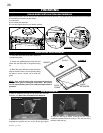
4. Apply high temperature sealant W573-0002 (not
supplied) to the outer edge of the
of the outter pipe of the air terminal
connector. Slip the 7" rigid vent
pipe over the outer pipe of the air
terminal connector and secure as
before. Trim the 7" rigid vent pipe
even with the end of the 4" rigid
vent pipe.
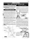
5. Thread the air terminal
connector / vent pipe assembly
down through the roof support and
attach, ensuring that a minimum
16" of air terminal connector will
penetrate the roof when fastened.
If the attic space is tight, we recommend threading
the Wolf Steel vent pipe collar or equivalent loosely
onto the air terminal connecter /
vent pipe assembly as it is passed
through the attic. The air terminal
connector must be located vertically
and plumb.
FIGURE 32
4” RIGID VENT
PIPE
7” RIGID VENT
PIPE
INNER
PIPE
HIGH
TEMPERATURE
SEALANT
AIR
TERMINAL
CONNECTOR
FIGURE 31
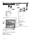
6. Remove nails from the shingles, above and to the
sides of the chimney. Place the fl ashing over the air terminal
connector and slide it underneath the sides and upper edge
of the shingles. Ensure that the air terminal connector is
properly centered within the fl ashing, giving a
3
/
4
" margin all
around. Fasten to the roof. Do NOT nail through the lower
portion of the fl ashing. Make weather-tight by sealing with
caulking. Where possible, cover the sides and top edges of
the fl ashing with roofi ng material.
7. Aligning the seams of the terminal and air terminal
connector, place the terminal over the air terminal connector
making sure the vent pipe goes into the hole in the terminal.
Secure with the three screws provided.
8. Apply a heavy bead of weatherproof caulking 2" above
the fl ashing. Note: Maintain a minimum 2” space between
the air inlet base and the storm collar. Install the storm collar
around the air terminal and slide down to the caulking. Tighten
to ensure that a weather-tight seal between the air terminal
and the collar is achieved.
9. Continue adding rigid vent pipe sections, sealing and
securing as above. Attach a 4" collapsed telescopic sleeve to
the last section of rigid piping. Secure with screws and seal.
Repeat using a 7" telescopic sleeve.
10. REAR VENT APPLICATION: Run a bead of high
temperature sealant around the outside of the 4" elbow. Pull
the adjustable pipe a minimum 2" onto the elbow. Secure with
3 screws. Repeat with the 7" telescopic pipe.
TOP VENT APPLICATION: Run a bead of high temperature
sealant W573-0007 (not supplied) around the outside of the
4" collar on the fi replace. Pull the adjustable pipe a minimum
of 2" onto the collar. Secure with 3 screws. Repeat with the
7" telescopic pipe.
11. In the attic, slide the vent pipe collar down to cover up
the open end of the shield and tighten. This will prevent any
materials, such as insulation, from fi lling up the 1" air space
around the pipe.
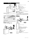
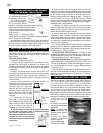
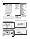
VERTICAL VENTING INSTALLATION
RESTRICTING VERTICAL VENTS
Vertical termination installations exiting either from the
rear or the top fl ue collar of the fi replace may display a
very active flame. If this appearance is not desirable,
the vent exit must be restricted to reduce the velocity of
the exhaust gases, thus slowing down the fl ame pattern
and creating a more traditional gentle appearance.
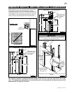
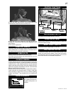
Remove the baffl e plate from the rear wall of the fi rebox,
exposing the fl ue gas outlet opening. Superimpose this outlet
hole with the smaller hole on the kit restrictor plate. Secure
with the two screws provided and replace the baffl e plate.
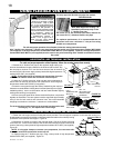
1. Remove the front
and the door from the
fi replace.
2. Remove the screws
securing the baffl e plate.
Figure 33.
Note: The baffle rests
on two screws that are
attached to the back of
the fi rebox.
3. Using the screws
supplied, attach the
restrictor plate as
shown in Figure 34.
4. Replace the baffl e.
RESTRICTOR PLATE
BAFFLE PLATE
SCREWS
FIGURE 33
FIGURE 34
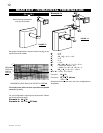
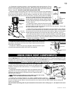
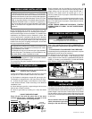
1. Follow the instructions
for "Horizontal Air Terminal
Installations", items 1 to 3.
2. Continue adding
components alternating 4"
and 7" vent pipes. Ensure
that all 4" vent pipes and elbows have
suffi cient vent spacers attached and each
component is securely fastened to the
one prior. Attach the 4" telescopic sleeve
to the vent run.
Repeat using a 7" telescopic sleeve.
Secure and seal as before. To facilitate completion, attach 4"
and 7" couplers to the air terminal.
3. Install the air terminal. See item 3 of the Horizontal Air
Terminal Installation. Extend the 4" telescopic sleeve; connect
to the air terminal connector. Fasten with self tapping screws
and seal. Repeat using the 7" telescopic sleeve.
FIGURE 30
EXTENDED HORIZONTAL AND CORNER
AIR TERMINAL INSTALLATION