


14
W415-0612 / C / 01.25.08
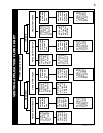
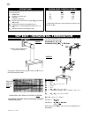
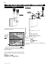
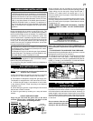
The shaded area within the lines represents acceptable
values for H
T
and V
T
.
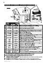
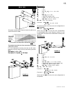
Example 6:
V
1
= 3 ft
V
2
= 6 ft
V
3
= 8 ft
V
T
=
V
1
+
V
2
+
V
3
=
3 + 6 + 8 = 17 ft
H
1
= 2 ft
H
2
= 2.5 ft
H
R
= H
1
+ H
2
= 2 + 2.5 = 4.5 ft
H
O
= .03(four 90° elbows - 90°)
= .03(90 + 90 + 90 + 90 - 90) = 8.1 ft
H
T
= H
R
+ H
O
= 4.5 + 8.1 = 12.6 ft
H
T
+ V
T
= 12.6 + 17 = 29.6 ft
Formula 1: H
T
< V
T
12.6 < 17
Formula 2: H
T
+ V
T
< 35 feet
29.6 < 35
Since both formulas are met, this vent confi guration is
acceptable.
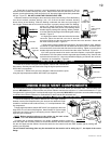
FIGURE 16
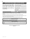
For vent confi gurations requiring more than zero 90° elbow
(top exit) or one 90° elbow (rear exit), the following formulas
apply:
Formula 1: H
T
< V
T
Formula 2: H
T
+ V
T
< 35 feet
ple venting confi gurations
See graph to determine the required vertical rise V
T
for the
required horizontal run H
T
.
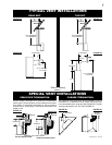
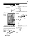
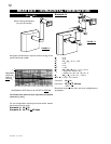
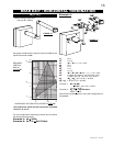
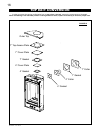
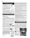
TOP OR REAR EXIT VERTICAL TERMINATION
90°
90°
90°
H
2
V
3
90°
FIGURE 17
V
1
0
5101520
35
10
20
30
3
17.5
17.5
(H
T
) < (V
T
)
H
1
V
2
REQUIRED
VERTICAL
RISE IN
FEET V
T
HORIZONTAL VENT RUN PLUS OFFSET IN FEET H
T