


9
W415-0405 / B / 03.25.04
This fireplace requires a 15 amp, 120 volt and 60 hz
circuit that is grounded to the electrical socket. The fire-
place should be on its own circuit. If there are other
appliances on the same circuit, this may cause the cir-
cuit breaker or fuse to blow when the fireplace heater is
in operation.
The unit comes with a 6' electrical cord, exiting the top
right side. Plan your installation to avoid the use of an
extension cord. If you require an extension cord, it must
be at least 16 awg wire and be rated for 2025 watts.
Electrical outlet wires must comply with local building
codes to reduce the risk of fire, electrical shock and
injury.
Do NOT use the fireplace if any part has been under
water.
Call a qualified service technician IMMEDIATELY to have
the fireplace inspected for damage to the electrical cir-
cuit.
If it is necessary to hard wire this fireplace, a qualifiedIf it is necessary to hard wire this fireplace, a qualified
If it is necessary to hard wire this fireplace, a qualifiedIf it is necessary to hard wire this fireplace, a qualified
If it is necessary to hard wire this fireplace, a qualified
electrician may remove the cord connection, and wireelectrician may remove the cord connection, and wire
electrician may remove the cord connection, and wireelectrician may remove the cord connection, and wire
electrician may remove the cord connection, and wire
this unit directly to the house hold wiring.this unit directly to the house hold wiring.
this unit directly to the house hold wiring.this unit directly to the house hold wiring.
this unit directly to the house hold wiring.
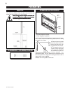
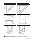
Permanently framing the fireplace with an enclosure, re-
quires the fireplace to be hardwired.
This fireplace must be electrically connected and grounded
in accordance with local codes. In the absence of local
codes, use the current CSA C22.1 CANADIAN ELECTRI-
CAL CODE in Canada or the ANSI/NFPA 70-1996 NATIONAL
ELECTRICAL CODE in the United States.
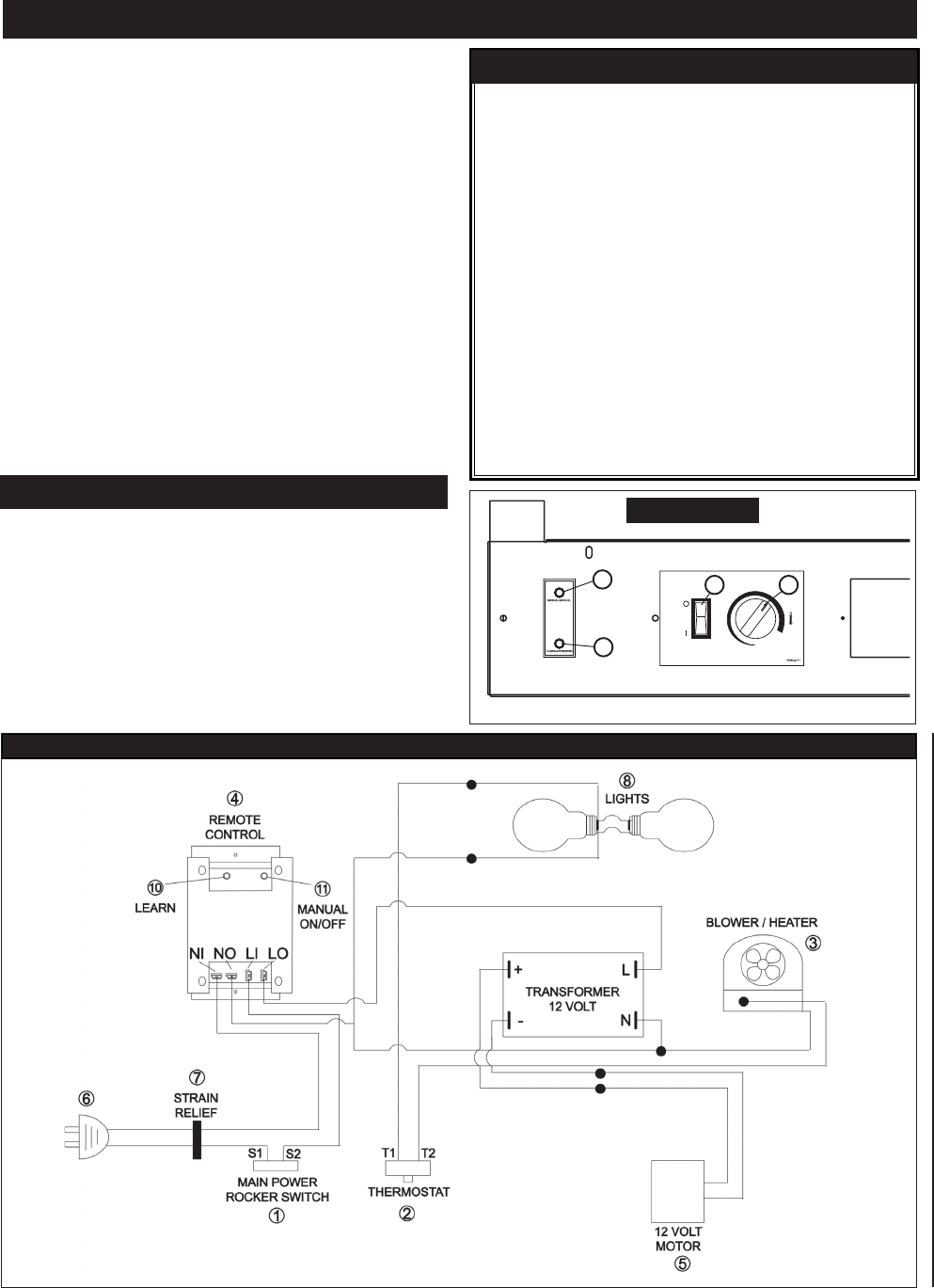
1.1.
1.1.
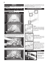
1.
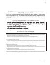
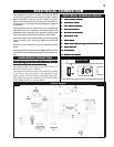
Power (Rocker Switch)Power (Rocker Switch)
Power (Rocker Switch)Power (Rocker Switch)
Power (Rocker Switch)
2.2.
2.2.
2.
Thermostat SwitchThermostat Switch
Thermostat SwitchThermostat Switch
Thermostat Switch
3.3.
3.3.
3.
Fan / Heater AssemblyFan / Heater Assembly
Fan / Heater AssemblyFan / Heater Assembly
Fan / Heater Assembly
4.4.
4.4.
4.
Main Circuit BoardMain Circuit Board
Main Circuit BoardMain Circuit Board
Main Circuit Board
5.5.
5.5.
5.
DC Motor (flame effect)DC Motor (flame effect)
DC Motor (flame effect)DC Motor (flame effect)
DC Motor (flame effect)
6.6.
6.6.
6.
Main Power CordMain Power Cord
Main Power CordMain Power Cord
Main Power Cord
7.7.
7.7.
7.
Strain ReliefStrain Relief
Strain ReliefStrain Relief
Strain Relief
8.8.
8.8.
8.
Flame Effect Light (two light sockets-Flame Effect Light (two light sockets-
Flame Effect Light (two light sockets-Flame Effect Light (two light sockets-
Flame Effect Light (two light sockets-
60 watts max60 watts max
60 watts max60 watts max
60 watts max
))
))
)
9.9.
9.9.
9.
Nylon Cable TieNylon Cable Tie
Nylon Cable TieNylon Cable Tie
Nylon Cable Tie
10. Learn Button10. Learn Button
10. Learn Button10. Learn Button
10. Learn Button
11. Manual on/off Button11. Manual on/off Button
11. Manual on/off Button11. Manual on/off Button
11. Manual on/off Button
ELECTRICAL CONNECTION
HARD WIRING CONNECTION
Electric Diagram
ELECTRICAL DIAGRAM LEGEND
10
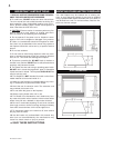
CONTROL PANEL
11
1 2