


6
W415-0297 / D / 04.03.03
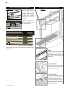
1. Move the fireplace into position and secure using the
nailing tabs and/or secure to the floor through the ¼"ø
holes located at either end of the base.
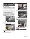
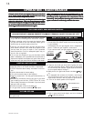
2. Install rigid black pipe, 1/2" type-L copper tubing or, if
local codes permit, a 3/8" flex connector and shutoff valve
to the gas line and the fireplace gas valve. Seal and tighten
securely. An adapter fitting is required between the gas
valve and the copper tubing or flex connector.
DO NOT KINK FLEX CONNECTOR.
3. Check for gas leaks by brushing on a soap and water
solution.
DO NOT USE OPEN FLAME.
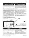
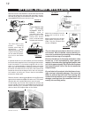
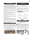
4. For ease of accessibility, an optional remote wall
switch or millivolt thermostat may be installed in a con-
venient location. Route a 2 strand, solid core millivolt wire
through the electrical hole located at the bottom left side of
the unit. The recommended maximum lead length de-
pends on wire size:
WIRE SIZE MAX. LENGTH
14gauge 100 feet
16gauge 60 feet
18gauge 40 feet
Attach the two leads to terminals 1 and 3 located on the
gas valve.
Do not connect either the wall switch, thermostat or
gas valve to electricity (110 volts).
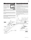
USING DOOR OPTION:
Purge all gas lines with the glass door of the fireplace
opened. Assure that a continuous gas flow is at the
burner before closing the door.
Unusually tight construction is defined as con-
struction where:
a) Walls and ceilings exposed to the outside atmos-
phere have a continuous water vapour retarder with a
rating of 1 perm (6 x 10
-11
kg per pa-sec-m
2
) or less with
openings gasketed or sealed, and
b) Weather stripping has been added on openable
windows and doors, and
c) Caulking or sealants are applied to areas such as
joints around window and door frames, between sole
plates and floors, between wall-ceiling joints, between
wall panels, at penetrations for plumbing, electrical, and
gas lines, and at other openings.
An unvented room heater is recommended for use as a
secondary heat source rather than as a primary source.
Gas combustion produces water vapour which could oc-
cur at the rate of approximately one ounce of water for
every 1,000 BTU/hr of gas input. During the cold weather
season, indoor humidity levels tend to be low. Conse-
quently, this water vapour can enhance the living space.
However if a problem should occur:
a) ensure sufficient combustion and circulation air
b) use a dehumidifier
c) do not use the unvented room heater as a primary
heat source
Without sufficient fresh air for proper operation, poor fuel
combustion can result. Carbon Monoxide is a result of
poor combustion.
If additional fresh air is required, use one of the
methods described in the National Fuel Gas Code,
ANSI Z223.1, Section 5.3 or the applicable local code.
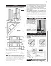
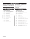
FIGURE 2
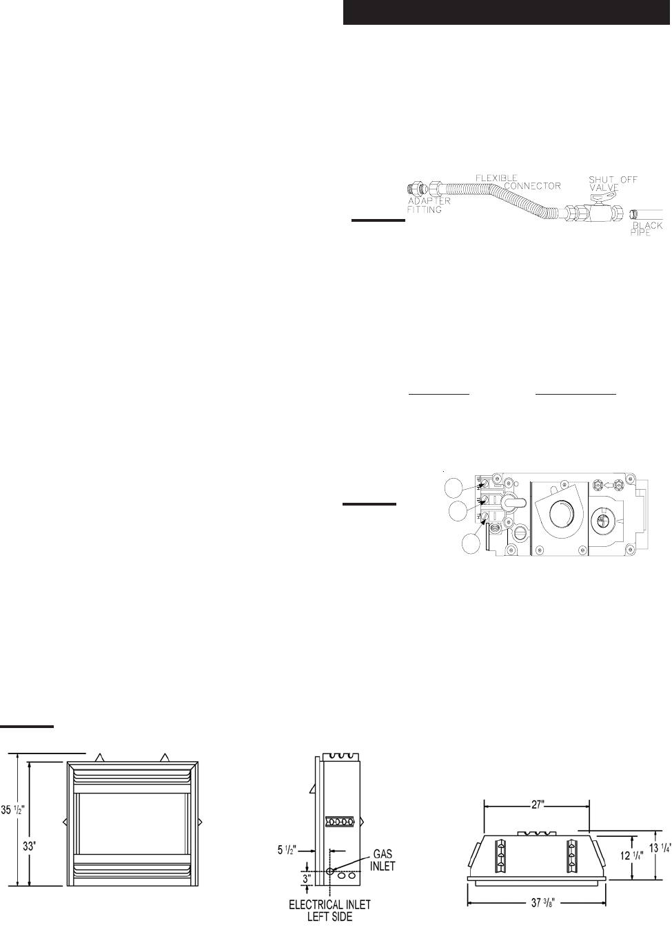
FIGURE 3
GAS INSTALLATION
FIGURE 4
P
I
P
I
L
O
T
3
1
2
N
O
L
O
T
H
I
L
O
F
F
O