12
RF Transmitter Programming
(For wireless systems only. Also see Quick Method, which follows)
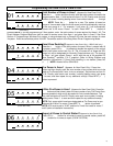
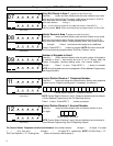
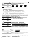
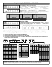
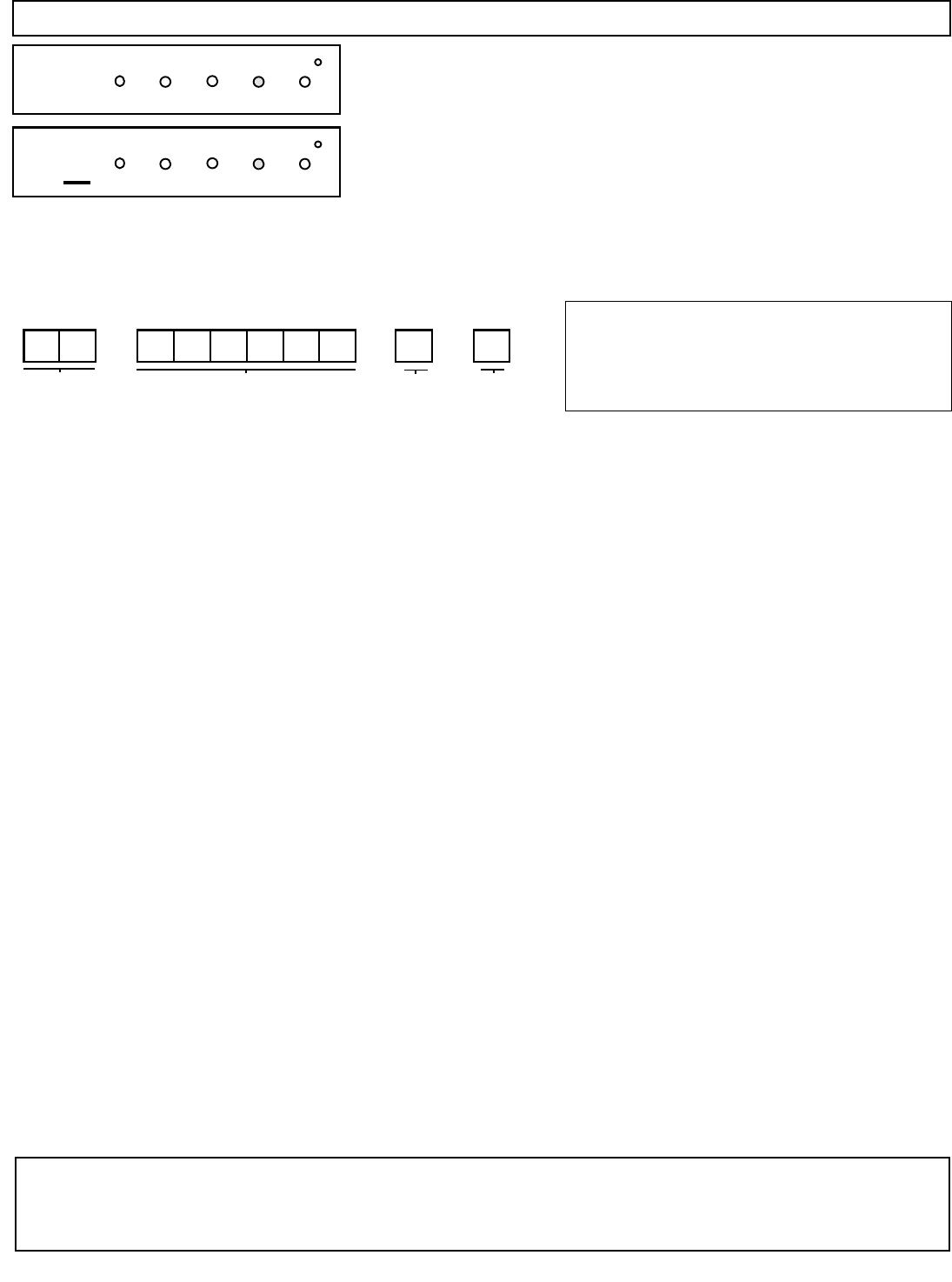
Press the A button and for each transmitter and directly enter:
1 The zone number (01–96) to which the transmitter will be mapped,
including leading zeros.
2 The 6-digit RF ID # printed on the transmitter and box.
3 The 1-digit checksum number (C) printed on the transmitter and box.
4 The Point number (1–4) (P); enter “9” for unsupervised (all points).
Press Jto save. Then go to step 1 to enter next transmitter. When all
transmitters are entered, press NEXT (E) button to proceed.
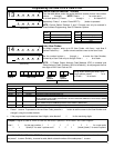
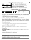
Quick Method. If a receiver is already installed in the panel, Napco transmitter wireless points can be programmed
automatically (“enrolled”) using the following procedure. NOTE: The transmitter point will be enrolled only if the signal
strength is 3 or greater.
1. Enter the zone number to which the transmitter point will be mapped.
2. Press the B button to enter the Enroll Mode. The red and green LEDs on the keypad will flash.
3. Open the loop of the point that is to be programmed (GEM-TRANS2 ).
4. Install the transmitter battery. The keypad will beep once to indicate that the point has been successfully enrolled.
Multi-point transmitters can be mapped to successive zones simultaneously (Example 1) or to selected zones point by
point (Example 2).
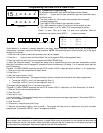
Example 1. A 4-point transmitter has the RF ID number 410078:1. Map the first three points to Zones 11–12, respectively.
1. Enter the Enroll mode as described in step 2 above.
2. Enter Zone “11”.
3. Open the loops of points 1 and 2.
4. Install the transmitter battery. The keypad will beep 3 times to indicate that three points have been programmed.
• Transmitter 410078:1, point 1 will be mapped to Zone 11.
• Transmitter 410078:1, point 2 will be mapped to Zone 12.
The keypad will now display Zone 12, the last zone enrolled.
Example 2. A 2-point transmitter has the RF ID number 287613:1. Map point 1 to Zone 6 and point 2 to Zone 9.
1. Enter the Enroll mode as described above.
2. Enter Zone “06”.
3. Open point-1 loop.
4. Install the battery. The keypad will beep once to indicate that one point has been programmed. (Transmitter 287613:1,
point 1 will be mapped to Zone 6.)
5. Enter Zone “09”.
6. Close point-1 loop and open point-2 loop.
7. Remove the transmitter battery, then re-install it. The keypad will beep once to indicate that one point has been
programmed. (Transmitter 287613:1, point 2 is mapped to Zone 9.)
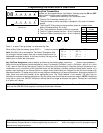
KEY FOB ZONE ASSIGNMENT: Key fobs can also be assigned to zones to allow multiple wireless panic buttons on one
alarm system, each reporting to a central station, or pager while having a description on the keypad that describes the
person holding the key fob, the location where the person holding the key fob is stationed, or the special purpose of the
key fob button being depressed. See the next page on Key fob Zone Assignment.
(Direct Entry)
07
INTERIOR
BYPASS FIRE/TBL SYS TBL CHIME
INTERIOR
BYPASS SYS TBL CHIME
FIRE/TBL
Zone # 6-digit RF ID # Checksum # Point #
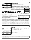
NOTE: When programming the ID Code number:
“A” = G 0 ; “B” = G 1 ;
“C” = G 2 ; “D” = G 3 ;
“E” = G 4 ; “F” = G 5 .
Programming the GEM-P3200 & GEM-P9600


