


16
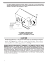
may require venting modifications (consult factory). The air inlet must be a minimum of 1'
vertically above the maximum snow level. It is very important that there are no other vents,
chimneys or air inlets in any direction for at least 4'.
All venting must be properly supported. The Munchkin is not intended to support any venting
whatsoever. All piping, glue, solvents, cleaners, fittings and components, must conform to ASTM
(American Society for Testing and Materials), and ANSI (American National Standards Institute). It is
recommended that you use one of the optional vent kits specifically designed for Munchkin installa-
tions, available from Heat Transfer Products, Inc. (KGAVT0601CVT [3 in.], KGAVT0501CVT [2 in.] or
V500 for the T50M/T80M or V1000 for the 80M/140M/199M). NOTE: When using the KGAVT601CVT
KIT, REMOVE THE 2 SCREENS FROM THE PROVIDED INLET TEE AND INSTALL THEM IN THE INLET
SOCKET AND OUTLET SOCKET (Y TEE CONNECTION) OF THE KIT PRIOR TO INSTALLING THE
SCHEDULE 40 PIPE AND GLUING.
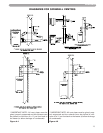
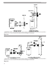
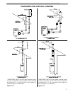
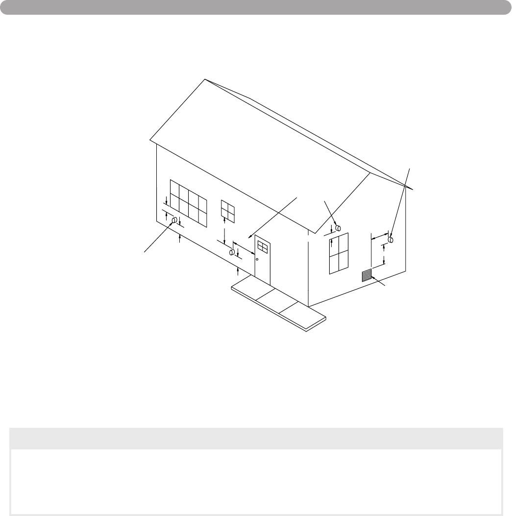
VENTING
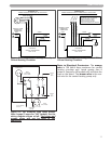
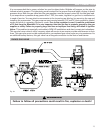
12 in.minimum
Forced air
inlet
G
rade
3 ft.minimum
Less
than
10 ft.
term
inal
(see 10.8.1)*
d
raft v
ent
M
echan
ical
C
12 in.minimum
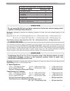
Direct vent terminal clearance
Minimum clearance, C
Input (Btu/hr)
4 ft.m
inim
um
12 in.minimum
minimum
ven
t term
inal
M
e
chanical draft
(see 10.8.2)*
4 ft.
Clearance (in.)
10,000 or less
10,001 to 50,000
Over 50,000
(see 10.8.3)*
6
9
12
For SI units: 1 ft = 0.305 m; 1 in. = 25.4 mm;
1 Btu/hr = 0.293 W
EXIT TERMINALS OF MECHANICAL DRAFT
AND DIRECT-VENT VENTING SYSTEM
* REFERENCE: THE NATIONAL FUEL GAS CODE
2002 EDITION
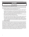
CAUTION
Flue Gas will condense as it exits the vent termination. This condensate can freeze on
exterior building surfaces which may cause discoloration of these surfaces.
Consideration should be given to the plume of condensation that exits the exhaust
which may affect the cosmetic appearance of the building.