


15
VENTING
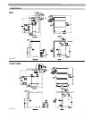
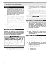
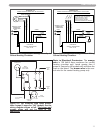
B. VENTING THE MUNCHKIN
The inlet pipe on the back of the cabinet should be 3" PVC schedule 40. It is very important that you
plan the location properly to eliminate long pipe runs and excessive fittings. Inlet pipe size must not
be reduced. Do not combine the inlet air with any other inlet pipe including an inlet to an additional
similar appliance. The joints must be properly cleaned, primed and cemented. The piping must also
be properly supported as per Local and National Standard Plumbing Codes. It is important that the
piping must be clean and free from burrs, debris, ragged ends and particles of PVC.
Exhaust piping should be sloped back to the connection on the Munchkin, at least ¼" per foot to
remove additional condensate that forms within the pipe. The total combined length of pipe (intake
piping plus exhaust piping added together) including elbow allowances intake and exhaust (each
elbow = 5' of pipe) should not exceed 85'. The combined vent length should not be less than a com-
bined length of 6' plus two 90 degree elbows. Choose your vent termination locations carefully. You
must also make certain that exhaust gas does not re-circulate back into the intake pipe. You must
place them in an open area and follow the following guidelines.
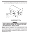
1) Never vent into a walkway, patio area, alley or otherwise public area less than 7' from the
ground. (See the following detail references Fig. A.10.8 in the National Fuel Gas Code 2002
“Exit Terminals of Mechanical Draft and Direct-Venting Systems”.)
2) Never vent over or under a window or over a doorway where the exhaust plume or conden-
sation liquid will cause obtrusive or dangerous conditions. (Or refer to National Fuel Gas
Code, CAN B149)
3) Never install a heat saver or similar product to capture waste heat from exhaust.
4) Always have a vent location at least 1' above maximum snow level.
5) Always have vent 1' above ground level, away from shrubs and bushes.
6) Follow local gas codes in your region or refer to National Fuel Gas Code, Can B149.
7) Always have at least 3' from an inside corner of outside walls.
8) Maintain at least 4' clearance to electric, gas meters, windows, exhaust fans, chimneys, inlets
or mechanical vents.
9) Very Important! The inlet air connection must be connected to outside air and should be
located no closer than 8" to the exhaust and no further than 36".
10) Always place screens in all openings in intake and exhaust to prevent foreign matter from
entering the Munchkin.
11) The vent intake and exhaust must be properly cleaned and glued for a pressure tight joint.
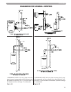
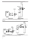
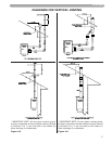
Several methods for venting the Munchkin can be found in Figures 4-1 thru 4-6 in this section.
Use these layouts as guidelines: certain site conditions such as multiple roof lines/pitches
DANGER
It is extremely important to follow these venting instructions exactly. Failure to do so
can cause severe personal injury, death or substantial property damage.
CAUTION
The following are code restrictions for the location of the flue gas vent terminal.
Compliance to these requirements doesn’t insure a satisfactory installation; good
common sense must also be applied. It is important to make sure that exhaust gases
are not recirculated into the inlet air of the Munchkin.