7
ELECTRICAL
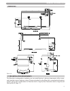
The electrical requirements are for standard 120 volts, 60 Hz 15 Amp service. This unit is wired with
#18 awg and fused for no more than 15 Amps.
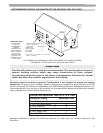
There are two ground points in the electrical compartment that must be connected to the building
ground system. Connect the building ground to the green ground screw and the green ground wire
inside electrical box provided.
The Incoming Power Supply is connected to the Black (Hot) and the White (Neutral).The Munchkin
Control board is polarity sensitive. If the polarity is reversed, the Munchkin control will not sense a
flame and lock out the system. The Orange and Brown wire are provided to the supply of 120 volts to
the Central Heating Circulator. Connect the Orange (Hot) and the Brown (Neutral) directly to the Central
Heating Circulator.
Connect the gray wires to your heating thermostat (TT) connection. Your thermostat heat anticipator
setting is .056 amp.
It is important that the electrical power is not turned on at this time. Double check all connections and then
turn the power on. The display that is provided with the Munchkin should now be reading the outlet
temperature. Note: see Part 6/Startup Procedure section in the manual to change the temperature setting
or run the heater.
DANGER
IT IS VERY IMPORTANT THAT THE BUILDING GROUND IS INSPECTED BY A
QUALIFIED ELECTRICIAN PRIOR TO MAKING THIS CONNECTION!
DANGER
The Orange wire for the Central Heating Circulator is Switched Hot and must have a
wire nut if not connected to the Central Heating Circulator. Failure to follow this
instruction will result in a short, and the Control Board will have to be replaced.
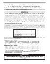
CAUTION
Electrical wiring on the Incoming Power and Central Heating Circulator shall be
connected directly to the intended connection source and not be connected together
inside the electric box provided. An Electrical Short will result and the Control board
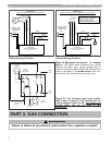
will have to be replaced! If Electrical Requirements of the Central Heating Circulator
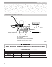
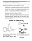
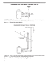
exceeds 4 amps (or 3 amps on HA models only) please follow the wiring diagrams on
Page 8, Figures 2-1, 2-2 and 2-3.
DANGER
IT IS EXTREMELY IMPORTANT THAT THIS UNIT BE PROPERLY GROUNDED!
CAUTION
Do not power zone valves directly from the heater transformer. Doing so will greatly
reduce the life of the transformer. Use a separate transformer sized to handle the total
electric load of all zone valves.


