


13
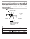
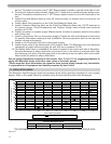
RECOMMENDED VENTING CLEARANCES PER THE NATIONAL FUEL GAS CODE*
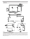
All venting must be properly supported. The Munchkin is not intended to support any venting
whatsoever. All piping, glue, solvents, cleaners, fittings and components, must conform to ASTM
(American Society for Testing and Materials), and ANSI (American National Standards Institute). It is
recommended that you use one of the optional vent kits specifically designed for Munchkin installa-
tions, available from Heat Transfer Products, Inc.
Friction Loss Equivalent Table for 4" or 6" vent
Fittings or Piping Equivalent Feet
4" or 6" 90 degree elbow = 5
4" or 6" 45 degree elbow = 3
4" or 6" Coupling = 0
4" or 6" air inlet tee = 0
4" or 6" Plastic Pipe = 1
4" or 6" V2000 vent kit = 0
Example: Installation requires the following material for both inlet and exhaust piping for the
Munchkin
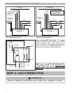
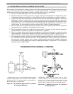
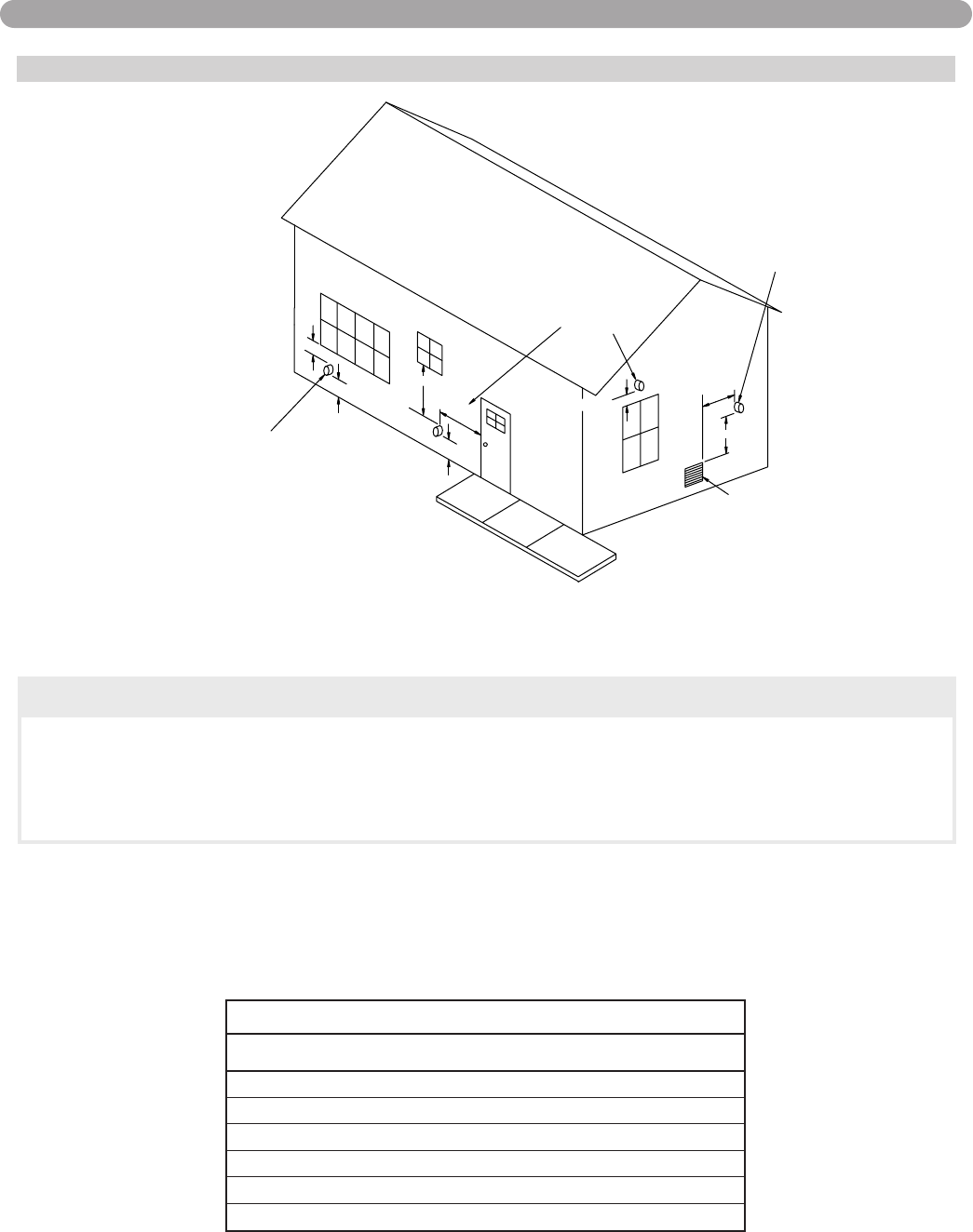
VENTING
12 in.m
inim
um
Forced air
inlet
G
rad
e
3 ft.minim
um
Less
than 10 ft.
term
in
al
(see 10
.8.1)*
d
ra
ft ven
t
M
e
ch
anical
C
12 in.minimum
Direct vent terminal clearance
Minimum clearance, C
Input (Btu/hr)
4 ft.m
inim
um
12 in.minimum
minimum
vent term
in
al
M
ech
anical d
raft
(see
10.8.2)*
4 ft.
Clearance (in.)
10,000 or less
10,001 to 50,000
Over 50,000
(see 10.8.3)*
6
9
12
For SI units: 1 ft = 0.305 m; 1 in. = 25.4 mm;
1 Btu/hr = 0.293 W
EXIT TERMINALS OF MECHANICAL DRAFT AND DIRECT-VENT VENTING SYSTEM
* REFERENCE: THE NATIONAL FUEL GAS CODE 2002 EDITION
CAUTION
Flue Gas will condense as it exits the vent termination. This condensate can freeze on
exterior building surfaces which may cause discoloration of these surfaces.
Consideration should be given to the plume of condensation that exits the exhaust
which may affect the cosmetic appearance of the building.
*IMPORTANT NOTE
HEAT TRANSFER
PRODUCTS
RECOMMENDS A
MINIMUM
CLEARANCE OF 4
FEET WHERE THE
PLUME CAUSED BY
THE UNIT MAY
OBSTRUCT VIEWS
OR AFFECT THE
COSMETIC LOOK OF
THE BUILDING.