OPERATION
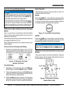
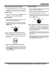
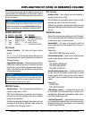
Full Load Current (FLC) Amps Dial A Setting
1. Set dial A pointer (Figure 16) to 10.5. This setting
represents the running amps of the pump. This
information can be located on the pump's nameplate
Reset Dial Setting
1. Depending on the application, Set dial B
pointer (Figure 16) to either or.
1. From the voltage source set the circuit breaker or quick
disconnect switch to the position.
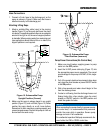
2. For manual operation of the pump, place the 3-position
operation switch (Figure 17) on the control box in the
position.
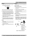
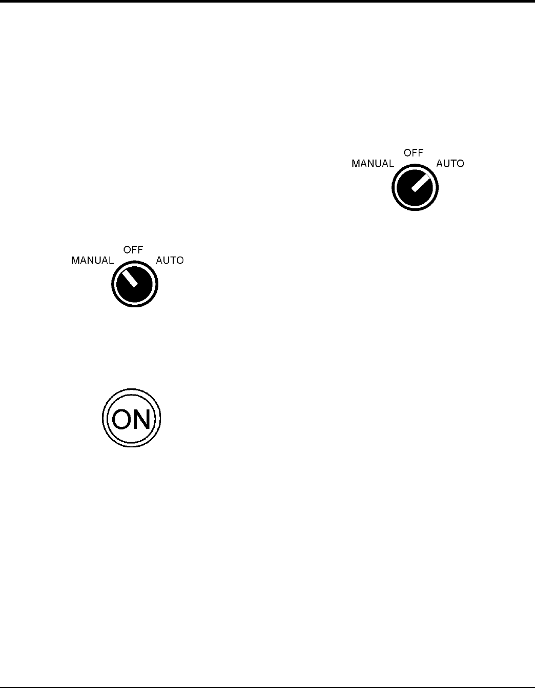
Figure 17. Manual-Off-On SW. (Man Position)
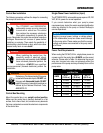
3. Verify that the indicator (Figure 18) on the control
box is LIT. This means that power is being supplied to
the control box.
Figure 18. Control Box Power ON Indicator
4. In the manual mode the pump will run continuously. Pay
close attention when running the pump in this mode.
Severe to the pump may occur if pump is
not immersed in water.
1. From the voltage source set the circuit breaker or quick
disconnect switch to the position.
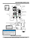
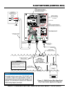
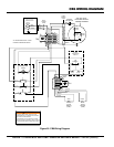
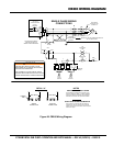
2. Make sure float switches have been connected to the
control box. References Figures 9,10 and 11.
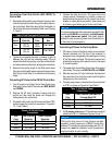
3. For automatic operation of the pump, place the
3-position operation switch (Figure 19) on the control
box in the position.
Figure 19. Manual-Off-On SW. (AUTO Position)
4. In the mode the pump will run as long as there
is a sufficient amount of water for the start float switch
to be activated. This water level is determined by the
setting of the float switches.
The stop float switch contacts will open when the
water level is low and power will be removed from the
pump's motor.
5. Once the water level has risen back to the appropriate
level the start float switch contacts will close and power
will be restored to the pump's motor.


