


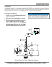
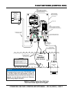
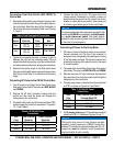
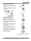
1. Remove the float switch input connector housing, then
route the float switch wires through the cable gland on
the control box. Attach the wires of the float switch to
the terminal block as indicated by Table 5 and Figures
7, 8 and 9.
2. Tighten the connector housing to ensure a tight fit
between the cord and the connector body. This will
prevent the cable from pulling out of the terminal block
and also prevent moisture from entering the control box.
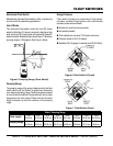
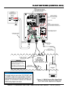
3. Determine the tether length of the float switch wires
then secure float switch wires to pump discharge hose.
See Figure 8 and Table 3 to determine the pumping
range.
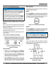
1. The AC power cord (input) should have three wires.
Each wire is color coded. The colors are, BLACK
and .
2. Remove the AC input connector housing from the
control box, then route the power cord through the
cable gland on the control box.
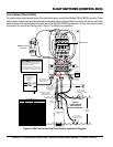
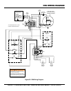
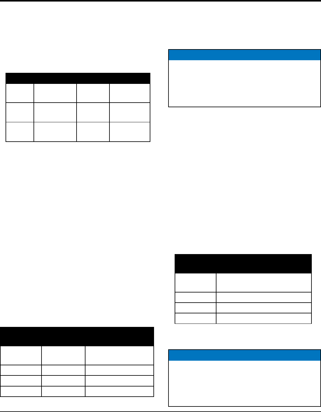
3. Connect the AC power cord to the terminal block (TB1)
located inside the control box as shown in Figures 9,
10, 11 and Table 6.
Table 5.
Switch
Terminal
Wire
Color
Control
Start
TB1-A1
TB1-A2
Black
White
CB6/CB200
Stop
TB1-A3
TB1-A4
Black
White
CB6/CB200
Table 6.
Connections
Wire
Color
CB6 Terminal
CB200 Terminal
BLACK TB1-AR (L1) TB1A-L1
RED TB1-AS (L2) TB1A-L2
GREEN TB1-GND TB1-GND
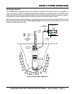
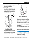
OPERATION
4. Connect the other end of the AC power cord to the
voltage source. Remember to provide a means of
disconnecting the power from the control box (circuit
breaker or quick disconnect switch). Also make sure
to provide a good earth ground to the control box
Connecting AC Power to the Pump Motor
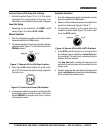
1. AC power is routed to the pump motor via a contactor/
thermal overload unit. The coil of the contactor is
energized or de-energized by the opening and closing
of the float switch contacts. The thermal overload unit
protects the windings of the electric motor in the event
of a stuck impeller.
2. The power cord should have three wires. Each wire is
color coded. The colors are , BLACK and .
3. Remove the pump AC input connector housing from
the control box, then route the power cord through the
cable gland on the control box.
4. Connect pump power cord to the thermal overload unit
and TB1 as shown in Figures 8, 9 and Table 7.
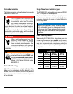
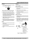
5. Install jumper wire between T2 of electronic overload
module and TB1-L3. Reference Figures 10 and 11.
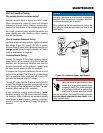
NOTICE
It is recommended that the power being supplied to the
control box be connected to a circuit breaker
or a quick disconnect switch. This safety feature
allows for quick removal of power from the control box
in the event of an emergency.
Connections
Wire
Color
Terminal Block TB1
BLACK T1-2 (L1)
RED T3-6 (L3)
GREEN TB1-GND
NOTICE
CB6 control box does not have thermal overload
capability. Install jumper wire (CB200 Control Box)
between T2 of electronic overload module and TB1-L3.
Jumper wire must be installed in order for electronic
overload module to work correctly.