


ST2010 SERIES SUBMERSIBLE PUMP • OPERATION AND PARTS MANUAL — REV. #3 (12/07/12) — PAGE 17
CONTROL BOX INSTALLATION
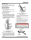
CONTROL BOX MOUNTING
Mount the control box in an upright vertical position. Make
sure the control box is securely fastened to a flat surface,
that is free of dust, dirt, moisture or any elements that
may contaminate or erode the electronic components of
the control box.
SINGLE-PHASE POWER INSTALLATION (INPUT)
The ST2010, ST2010A, ST2010CUL, and ST2010TCUL
submersible pumps require 115 V, 60 Hz, single-phase
power for normal operation. The ST2010B requires 230 V,
60 Hz, single-phase power.
If you cannot determine what your pump's power
requirements are, look at the vendor supplied identification
name tag attached to the pump or contact Multiquip's
Service/Technical Assistance department.
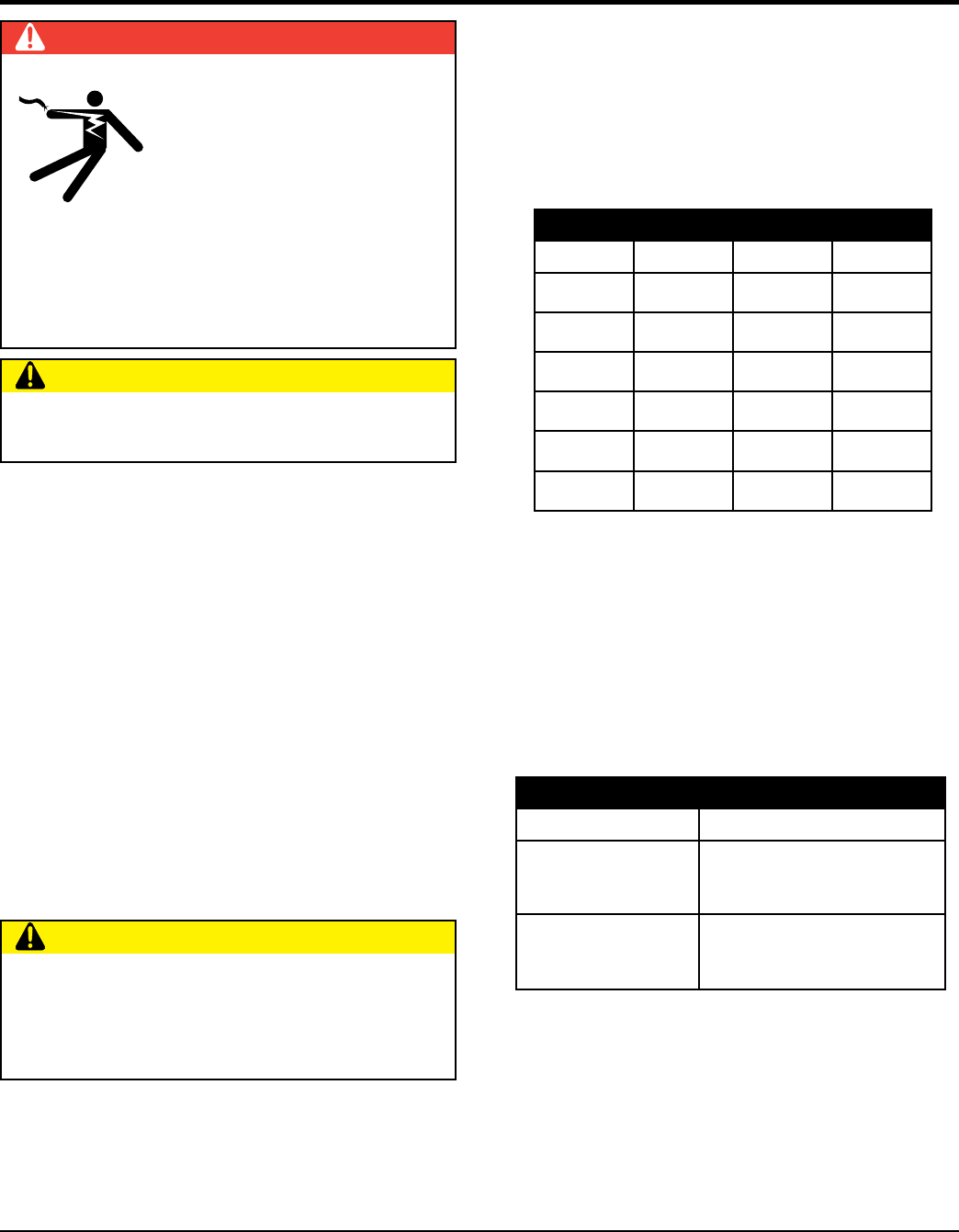
DANGER
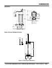
The ST2010 Series submersible
pumps are designed to work with a
control box. The control box contains
the necessary electronics (float
switch connections) to operate
the pump. Remember the control
box contains hazardous voltages.
Disconnect all sources of power
before installing or servicing. There exists the possibility
of electrocution, electric shock or burn, which can cause
severe bodily harm or even death!
CAUTION
This control box should only be installed or serviced by
a licensed electrician or qualified personnel.
CAUTION
Applying incorrect power (voltage phasing) to the
submersible pump can cause severe damage to the
pump. Please make sure that the correct voltage and
phase are transferred to the pump at all times.
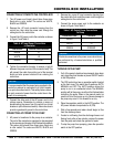
POWER CORD REQUIREMENTS
When routing the 115 VAC/230V, 60 Hz, single-phase power
via a power cord to the control box, always use the correct
wire size. Please refer to Table 4 below (Cord Length/Wire
Size) to determine the correct wire size. Incorrect wire size
can adversely affect the performance of the pump.
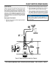
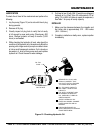
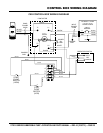
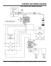
CONNECTING DUAL FLOAT SWITCH (SW-1WOP)
TO CONTROL BOX
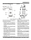
1. Remove the float switch input connector housing, then
route the float switch wires through the cable gland on
the control box. Attach the wires of the float switch to
the terminal block as indicated by Table 5, Figure 7
and Figure 8.
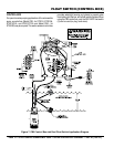
2. Tighten the connector housing to ensure a tight fit
between the cord and the connector body. This will
prevent the cable from pulling out of the terminal block
and also prevent moisture from entering the control box.
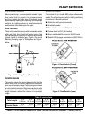
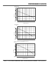
3. Determine the length of the float switch wires, then
secure float switch wires to pump discharge hose. See
Figure 3 and Table 3 to determine the pumping range.
Table 4. Cord Length and Wire Size
AMPS 50 FT. 100 FT. 150 FT.
6 16 AWG 16 AWG 14 AWG
8 16 AWG 14 AWG 12 AWG
10 16 AWG 14 AWG 12 AWG
12 14 AWG 14 AWG 12 AWG
14 14 AWG 12 AWG 10 AWG
16 12 AWG 12 AWG 10 AWG
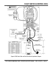
Table 5. Float Switch Connections
Float Switch Terminal Block Number
START
TERMINAL 1 (BLACK)
TERMINAL 2 (WHITE)
STOP
TERMINAL 7 WHITE)
TERMINAL 8 (BLACK))