ST2010 SERIES SUBMERSIBLE PUMP • OPERATION AND PARTS MANUAL — REV. #3 (12/07/12) — PAGE 13
FLOAT SWITCH (PIGGY-BACK)
FLOAT SWITCH
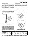
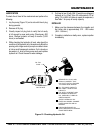
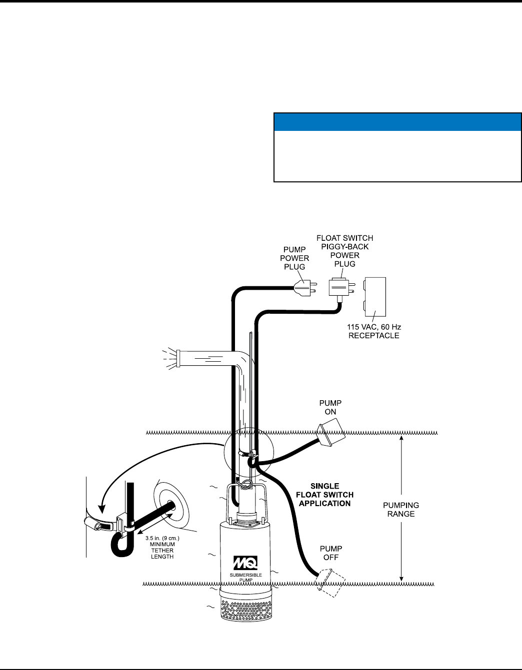
Single or dual control float switches (Figure 6) can be used
for the unattended operation of the submersible pump.
When using the piggy-back power configuration (plug),
the ST-2010 series pumps DO NOT require the use of a
control box. In this configuration (piggy-back), the SW-1
(single float switch) or SW-2 (dual float switch) are required.
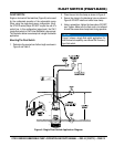
The illustration below is an example of a single float switch
application.
Mounting The Float Switch
1. Determine the required cord tether length as shown in
Figure 6 and Table 3.
2. Place the cord into the clamp as shown in Figure 6
3. Secure the clamp to the discharge hose as shown in
Figure 6. DO NOT install cord under hose clamp.
4. Using a screwdriver, tighten the hose clamp. DO NOT
over- tighten. Make sure the float cord is not allowed
to touch the excess hose clamp band during operation.
NOTICE
Figure 6 shows a single float switch application. For
dual float switch capability use a Model SW-2 mercury
type float switch.
Figure 6. Single Float Switch Application Diagram


