


PAGE 36 — HTN 31V
HTN-SERIES • RIDE-ON POWER TROWEL — OPERATION MANUAL — REV. #0 (06/06/07) — PAGE 36
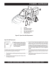
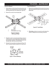
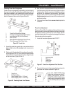
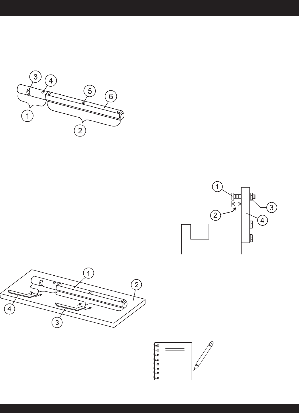
Trowel Arm Adjustment
Shown in (Figure 39) is the adjustment fixture with a trowel arm
inserted. As each trowel arm is locked into the fixture, the arm bolt
is adjusted to where it contacts a stop on the fixture. This will
consistently adjust all of the trowel arms, keeping the finisher as
flat and evenly pitched as possible.
1. Locate the trowel arm adjustment tool P/N 9177.
Figure 37. Trowel Arm Adjustment Tool Side View
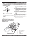
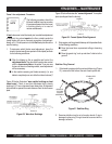
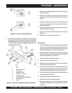
NOTE
Arms with CLOCK-WISE blade
rotation use the fixture arm in the UP
position (A in Figure 38). Arms with
COUNTER CLOCK-WISE blade
rotation use the fixture with the fixture
arm in the DOWN position. (B in Figure
38).
2. Ensure the fixture arm is in the proper setting (up or down) for
your trowel arm rotation as shown in Figure 38.
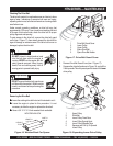
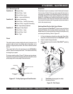
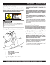
1. Use a thick steel plate, granite slab or any surface which is
true
and
flat
, to check all
six sides
of each trowel arm for
flatness.
2. Check each of the six sides of the trowel arm (hex section).
A feeler gauge of .004" (0.10 mm) should not pass between
the flat of the trowel arm and the test surface along its length
on the test surface. (Figure 36 item 3) .
Figure 36. Checking Trowel Arm Flatness
HTN-SERIES — MAINTENANCE
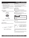
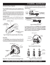
Checking Trowel Arm Straightness
Trowel arms can be damaged by rough handling, (such as dropping
the trowel on the pad), or by striking exposed plumbing, forms, or
rebar while in operation. A bent trowel arm will not allow the trowel
to operate in a smooth fluid rotation. If bent trowel arms are suspect,
check for flatness as follows, refer to Figures 35 and 36:
1 Trowel Arm
2 Flat Test Surface
3 Feeler Gauge (.004 in. / 0.10 mm)
4 Feeler Gauge (.005 in. / 0.127 mm))
3. Next, check the clearance between the round shaft and the
test surface as one of the flat hex sections of the arm rests on
the test surface. Rotate the arm to each of the flat hex sections
and check the clearance of the round shaft. Use a feeler
gauge of .005" (0.127 mm). Each section should have the
same
clearance
between the round of the trowel arm shaft
and the test surface.
4. If the trowel arm is found to be
uneven
or
bent
, replace the
trowel arm.
1 Trowel Arm Round Shaft Section
2 Trowel Arm Hexagonal (Hex) Shaft Section
3 Lever Mounting Slot (Left Arm Shown)
4 Roll Pin Hole
5 Blade Attachment Bolt Hole (One of Three)
6 Flat of Hexagonal Shaft (Top of Arm)
Figure 35. Trowel Arm
1 Adjustment Bolt
2 "Distance"
3 Locking Nut
4 Fixture Arm
SIDE VIEW