


PAGE 34 — HTN 31V
HTN-SERIES • RIDE-ON POWER TROWEL — OPERATION MANUAL — REV. #0 (06/06/07) — PAGE 34
■
Does the trowel have a perceived rolling or bouncing
motion?
■
Does the guard ring “rock up and down” relative to the
ground?
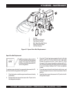
2. Start engine, and bring trowel blades up to full speed and look
for the following conditions:
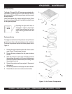
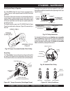
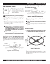
Stabilizer Ring Removal
1. If the trowel is equipped with an outer stabilizer ring (Figure
31), remove the four bolts at the end of each spider arm.
Figure 31 Stabilizer Ring
2. Examine stabilizer ring for out of round or bends. If ring is
damaged, replace ring. If ring is found to be correct with no
damage, set aside.
STABILIZER
RING
REMOVE
TO FREE
SPIDER
ASSEMBLY
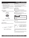
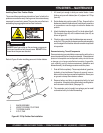
Figure 29. Worn Arm Bushings
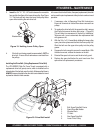
Trowel Arm adjustment Procedure
The following procedure should be
followed to adjust trowel arms when
it becomes apparent that the trowel
is finishing poorly or in need of
routine maintenance.
A
level
, clean area to test the trowel prior to and after adjustement
is essential. Any unlevel
spots
in the floor or debris under the
trowel blades will give an incorrect perception of adjustment.
Ideally, a 5' x 5' three-quarter inch thick
flat
steel plate should be
used for testing.
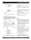
1. To determine which blades need adjustment, place the
trowel in the test area (three-quarter inch thick plate) and look
for the following conditions:
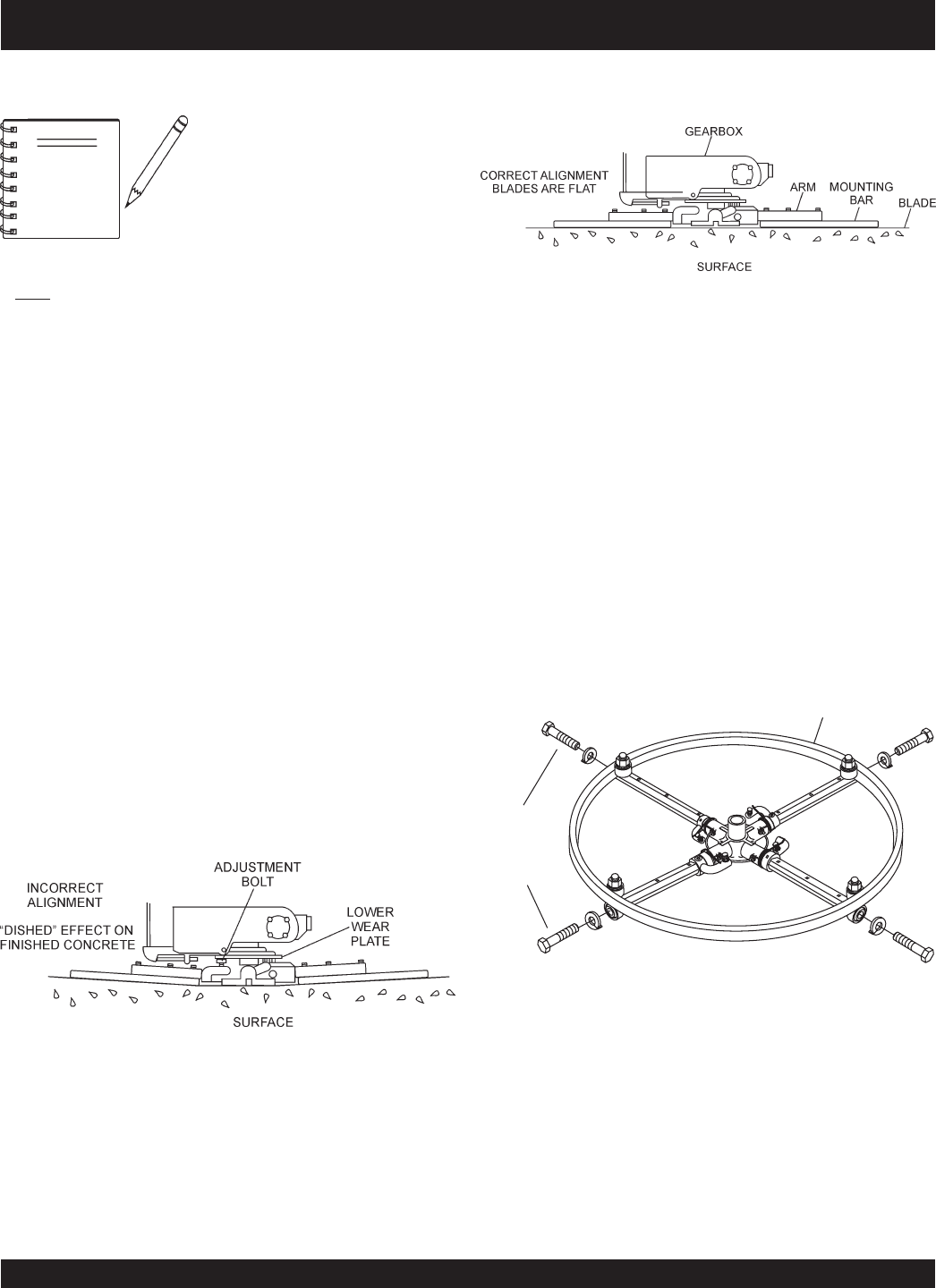
■
Pitch the blades as flat as possible and look at the
adjustment bolts
. They should all barely make contact
with the
lower wear plate
on the spider. If you can see
that one of them is not making contact, some adjustment
will be necessary.
■
Is the machine wearing out blades unevenly (i.e. one
blade is completely worn out while the others look new)?
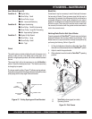
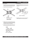
Figure 29 below illustrates "
worn spider bushings or bent
trowel arms
". Check to see that adjustment bolt is barely
touching (0.10" max. clearance) lower wear plate. All alignment
bolts should be spaced the same distance from the lower wear
plate.
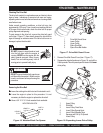
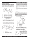
Figure 30 below illustrates the "
correct alignment
" for a spider
plate (as shipped from the factory).
Figure 30. Correct Spider Plate Alignment
HTN-SERIES — MAINTENANCE
NOTE