


62D4036
10
BBV, SBV Series Natural Vent Gas Fireplaces
VENT INSTALLATION
INSTALLATION PLANNING
“B” VENT PIPE
See venting installation instructions provided by the B-
Vent manufacturer.
NOTE: This APPLIANCE MUST BE INSTALLED using
“B” vent type pipe that has been listed by a nationally rec-
ognized testing agency.
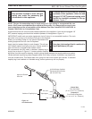
Refer to B-Vent Pipe Sizing chart for proper elbow offset
runs.
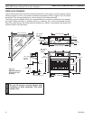
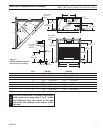
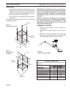
Chimney centerline dimensions are referenced on Pages
6 & 7, Figures 2 & 3.
• Minimum vertical chimney height - 8’ as measured
from top of unit to top of termination.
• Minimum vertical height - 40’ as measured from top
of unit to top of termination.
• Minimum chimney height with two (2) 90° elbows
- 8’.
• Elbow requirements: Allow a maximum of two (2)
90° elbows or four (4) 45° elbows per installation.
NOTE: Two (2) 45° elbows = one (1) 90° elbow
• Horizontal run must never exceed 50% of the height
of the vent system. Horizontal runs are measured
center pipe to center pipe.
• Horizontal runs must have a minimum 1/4” rise per
foot and may not run level or down hill.
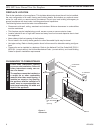
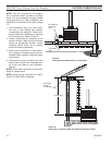
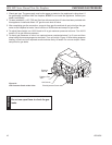
Attaching 4” Flue to BBV:
• The first section of B-vent flue should overlap
the appliance collar. The appliance collar may be
crimped to ease the installation of the first section
of flue.
• Do not penetrate the pipe inner liner with sheet met-
al screws. Attach the initial flue section to the top
of the firebox chassis with 1/4” self-tapping screws
and plumbers strap. Attach the strap toward the
bottom of the flue section and pull taut for proper
tension to the firebox.
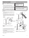
Attaching 6” Flue to SBV:
• The 6” appliance collar is slightly larger that the in-
ner wall of most B-vent 6” pipe sections. Install the
first section of B-vent by slipping the flue’s inner
wall tot he inside of the appliance collar. The B-vent
outer wall will slip to the outside of the appliance
collar.
• Do not penetrate the pipe inner line with sheet met-
al screws. Attach the initial flue section tot he top
of the firebox chassis with 1/4” self-tapping screws
and plumber’s strap. Attach the strap toward the
bottom of the flue section and pull taut for proper
tension to the firebox.
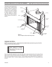
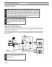
Support the Pipe
• Support horizontal runs a minimum of every five (5)
feet. Refer to vent manufacturer’s instructions for
proper support on vertical runs (45° or less).
• Support offsets so the weight of the pipe is not bear-
ing down on the elbows.
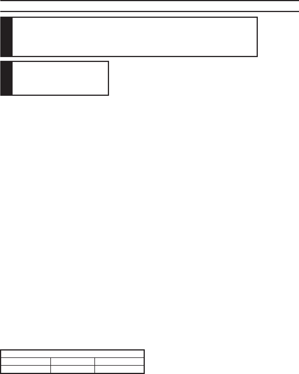
WARNING
Read all instructions completely and thoroughly before attempting installation.
Failure to do so could result in serious injury, property damage or loss of life.
Operation of improperly installed and maintained venting system could result in
serious injury, property damage or loss of life.
NOTICE
Failure to follow these in-
structions will void the war-
ranty.
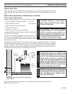
INSTALLATION PRECAUTIONS
Consult local building codes before beginning the instal-
lation. The installer must make sure to select the proper
vent system for installation. Before installing vent kit, the
installer must read this fireplace manual and vent kit in-
structions.
Only a qualified installer/service person should install
venting system. The installer must follow these safety
rules:
• Wear gloves and safety glasses for protection.
• Use extreme caution when using ladders or when
on rooftops.
• Be aware of electrical wiring locations in walls and
ceilings.
The following actions will void the warranty on your vent-
ing system:
• Installation of any damaged venting component.
• Unauthorized modification of the venting system.
• Installation of any component part not manufac-
tured or approved by MHSC.
• Installation other than permitted by these instruc-
tions.
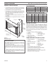
B-Vent Pipe Sizing
BBV400 SBV400 SBV500
4” 6” 6”