


73D0024 27
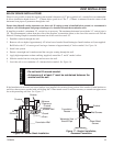
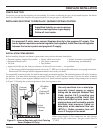
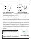
120 VAC
60Hz
JUNCTION BOX
Factory Supplied
Not Supplied
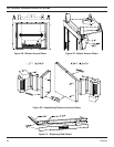
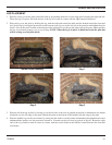
7. Remove the access covers on the right and left side walls of the firebox toward the front by unfastening the screws.
NOTE: The access covers are not identical. See Figure 28
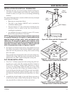
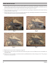
8. Two screws are already mounted to each cover which would be utilized to mount the blower to the plate. Unfasten the
two screws and mount the blower bracket assemblies. See Figure 30.
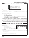
9. Consult blower wiring diagram and start the assembly. It is helpful to wire the right blower, the speed control, the fan
limit switch, and the power cord first. Then plug in the power cord to the junction box and secure the right cover plate/
blower assembly to the side of the firebox. See Figure 27 & 27a
10. Assemble the wire clips provided with the blower kit to the right and left sides of the fireplace through existing holes on
right and left.
11. Run the wire harness down the right and snap wires into the clips assembled in #10. Run the two wires along the glass
track, on the floor of the unit, in front of the firebox
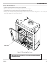
12. Snap the fan limit switch behind the clip already assembled to the side of the firebox on the front right hand side. See
Figure 29.
13. Secure the left access plate/blower assembly to the left side of the firebox. Run the two wires mentioned earlier up the
left firebox wall and snap wires into clip assembled in #10 on the outer shell wall. Make the connection to the left blower.
Replace the refractory and hearth refractory (pull away from burner toward the front).
14. Replace side panels attached to the glass frame assembly with the louvered side panels provided with the blower kit by
unfastening the four nuts for each cover door. (Do not overtighten or stud may break off.) Use three metal clip screws
provided with kit to secure the wire assembly in the front beneath the access cover. See Figure 7.
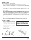
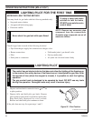
15. Install the speed control (rheostat switch) on the side above the existing one used for the light (discard the plate sent with
the switch as it will not be needed.
16. Replace logs.
17. Replace the glass.
18. Replace the front plate below the glass frame. NOTE: The front plate hides the wire harness in the front.
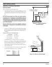
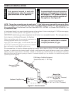
Figure 27a - Blower Wiring Diagram
OPTIONAL FAN/BLOWER SYSTEM
Electrical Grounding Instructions: This appliance is equipped with a
three-prong (grounding) plug for your protection against shock hazard
and should be plugged directly into a properly grounded three prong
receptacle.
WARNING
Figure 27 - Junction Box Wiring Diagram
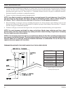
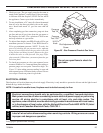
Figure 27b - Location of White
Dial on Speed Control
Failure to replace the access cover with the one provided with
the blower kit, and then running the blower, will cause excessive
temperatures and could cause a fi re, property damage and/or
loss of life.
WARNING