


73D0024 21
10
1
/
2
"
10
1
/
2
"
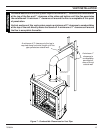
VENT INSTALLATION
INSTALLATION FOR VERTICAL TERMINATION
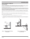
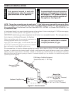
1. Determine the route your vertical venting will take. If ceiling joist,
roof rafters or other framing will obstruct the venting system,
consider an offset. See Figure 20 to avoid cutting load bearing
members.
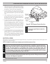
For optimal flame appearance, a restrictor disk is necessary on straight
vertical runs of 10' of more.
• Runs may not incorporate elbows.
• The disk is part number 56D3027 and is included in
installation manual packet.
• Drop the disk into a 5" inner collar before installing the first
section of flue or install at the last section before
installing the termination.
• An additional disk may be installed on runs of 35' or more.
Rotate disks perpendicular to each other.
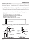
NOTE: Pay special attention to these installation instructions
for required clearances (air space) to combustibles when
passing through ceilings, walls, roofs, enclosures, attic
rafters, etc. Do not pack air spaces with insulation. Also
note maximum vertical rise of the venting system and any
maximum horizontal offset limitations. Offsets must fall
within the parameters shown in Figures 19 and 20.
2. Set fireplace in desired location. Drop a line plumb down from
the ceiling to the position of the flue exit. Mark the center point
where the vent will penetrate the ceiling. Drill a small locating
hole a this point.
Drop a plumb line from the inside of the roof to the ceiling locat-
ing hole in the ceiling. Mark the center point where the vent will
penetrate the roof. Drill a small locating hole at this point.
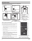
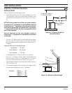
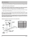
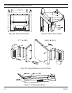
FLAT CEILING INSTALLATION
1. Cut a 10
1
/2" (241mm) square hole in the ceiling using the locat-
ing hole as a center point The opening should be framed to
10
1
/2"x10
1
/2" (241mm x 241mm) inside dimensions as shown
in Figure 22 using framing lumber the same size as the ceiling
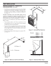
joist. If the area above the ceiling is an insulated ceiling or a
room, nail firestop from the top side. This prevents loose insula-
tion from falling into the required clearance space. See Figure
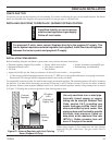
21. Otherwise, install firestop below the framed hole. See Figure
22.
2. Assemble the desired lengths of pipe and elbows necessary to
reach from the burner system flue up through the firestop. Be
sure pipe and elbow connections are fully twist-locked.
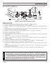
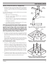
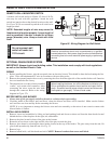
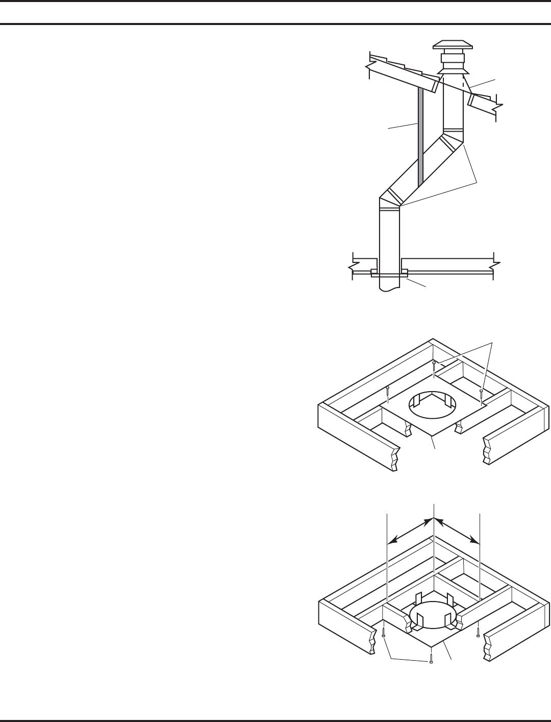
Figure 20 - Offset with Wall Strap and 45°
Elbows
Roof
Flashing
Wall
Strap
45° Elbows
Ceiling Firstop
Figure 21 - If Area Above is a Room, Install
Firestop above Framed Hole as Shown
Figure 22 - If Area Above is Not a Room, Install
Firestop above Framed Hole as Shown
Firestop
Nails
Nails
Firestop