


54D5031 27
FLEX VENT INSTALLATION
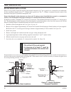
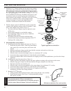
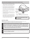
Figure 4 — Typical pipe connection
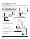
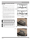
Figure 3 —
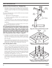
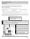
Typical vertical fl ex vent installation
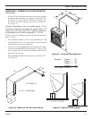
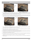
Figure 5 —
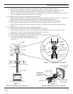
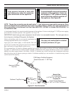
Typical horizontal fl ex vent installation
Termination
cap
Storm collar
Flashing
Rigid pipe
length
Flex to pipe
adapter
(FPA/8)
Fire stop
UL1777 fl ex pipe
DVFA/8 Adapter
Roof support
UL1777
Flex vent
Monessen horizontal
vent termination
Gear
clamps
1¾ in. fl exible pipe
and termination outer
collar overlap
Securing screws
(three places
equidistant, just
above gear clamp)
Termination to fl ex
adapter (FTA7/8)
UL1777
Flex vent
Securing
screws
(3 places
equidistant
just above
gear clamp)
Gear clamp
1¾ in. fl exible pipe
and adapter outer
collar overlap
Rigid pipe
length
Gear
clamp
Flex to pipe
adapter
(FPA/8)
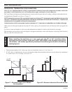
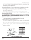
3. Do not allow the fl exible vent to bend in radius tighter than 5" (127mm). Refer to Figure 2.
4. Horizontal runs of fl exible vent shall be supported at maximum 2 foot intervals; vertical runs, fi ve feet
intervals. Metal strapping, properly secured, is an acceptable means to support the fl exible vent.
5. Flexible vent spacers are to be installed at intervals prescribed by the fl exible vent manufacture; and in such a
way as to maintain concentric inner and outer vent spacing.
D. Attaching fl exible venting to vertical termination assemblies.
1. When using Simpson pipe, a MHS fl ex-to-pipe adaptor and/or rigid pipe section(s) is required to connect the
fl exible vent assembly to the vertical termination by using three self penetrating screws.
2. Review Figure 4 and corresponding instructions for proper overlap, clamp and screw placement.
3. Three each self penetrating screws are drilled opposite one another and below the gear clamp.
4. Use only listed and approved terminations and accessories, installed per the installation instructions and
Figure 3.
E. Installing fl exible venting to horizontal termination assemblies.
1. Connect the 4" fl exible vent to the horizontal termination as in Figure 5.
2. Slide termination cap adapter ring over the termination cap’s outside pipe and secure with three screws.
3. Connect the 7" fl exible vent to the termination adapter ring as in Figure 5.
4. Review Figure 5 for proper overlap and clamp placement
5. Three each self penetrating screws are drilled opposite one another and below the gear clamp.
6. Use only listed and approved terminations and
accessories, installed per the termination instructions
and Figure 5.