


26 54D5031
FLEX VENT INSTALLATION
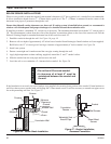
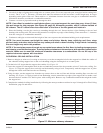
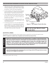
Flex vent pipe spacers: Refer to manufacturer’s
specifi cations for correct positioning of the spacer springs to
maintain proper distance between inside and outside pipe.
NOTE
UL1777
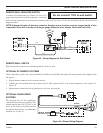
Flex vent
Securing screws
(3 places
equidistant just
above gear
clamp)
Gear clamps
DVFA/8
inner adapter
outer adapter
Appliance starting
collar
1¾ in. fl exible pipe
and adapter outer
collar overlap
UL1777
Flex vent
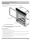
5" radius
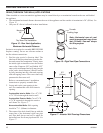
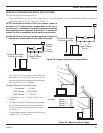
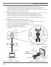
Figure 1 —
Typical appliance connection
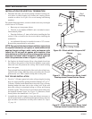
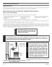
Figure 2 —
Minimum radius for fl ex vent section
1. Flexible UL1777 listed venting may be used in any venting
application where rigid direct vent components can be used.
All restrictions, clearances and allowances that pertain to
the rigid piping apply to the fl exible venting. Flex kits may
not be modifi ed. Flex kits may be added to the end of a vent
run made of rigid vent sections using pipe manufacturer’s
approved fl ex to pipe adapters. This may occur only if doing
so does not violate any of the venting length, height,
routing, horizontal to vertical ratio requirements or
clearance considerations detailed in this manual.
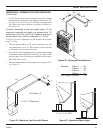
2. The fl ex adapter starter kit (DVFA/8) is used to attach fl ex
venting to the appliance starting collar. It includes 4" inner
and 7" outer adapter rings (refer to Figure 1).
• The inner and outer adaptor rings are required to start
all fl ex runs.
• Never install damaged or torn fl exible venting.
• Over tightening clamps may rip, tear, or otherwise
damage fl exible venting.
• The adaptor kit does not include individual pipe
sections which may be purchased separately. (UL1777
listed type fl ex venting only.)
3. Start the fl exible vent as follows—
A. Installing the inner fl ex adaptor and pipe (see Figure 1).
1. Insert the long side of the 4" inner ring inte exhaust
pipe, gently tap to seat into place, and secure with
screws.
2. Slide the small gear clamp over the inner fl exible vent pipe, and push out of the way.
3. Pull and extend the inner fl exible vent.
4. Slide the inner vent onto the adapter collar, for a minimum 1¾" overlap.
5. Locate the clamp at approximately ¾" from the fl ex end and tighten.
6. Secure the clamped inner section with three self tapping screws, drilled equidistance, just above the clamp
perimeter.
B. Installing the outer fl ex pipe (refer to Figure 1).
1. Firmly insert the outer adapter ring into the outer appliance starting collar and secure with screws.
2. Slide the large gear clamp over the outer fl exible vent pipe, and push out of the way.
3. Pull and extend the outer fl exible vent.
4. Slide the outer vent onto the appliance collar outer adapter for a minimum 1¾" overlap.
5. Locate the clamp at approximately ¾" from the fl ex end and tighten.
6. Secure the clamped outer section with three self tapping screws, drilled
equidistant, just above the clamp perimeter.
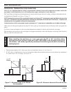
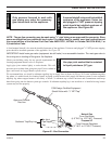
C. Routing UL1777 fl ex pipe.
1. Always maintain the required clearance when routing the fl ex vent assembly.
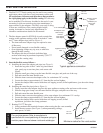
2. Install fi restop spacers (see Figure 3) when penetrating ceilings,
attic spaces, or walls.