


12
8
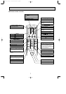
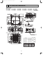
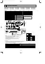
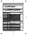
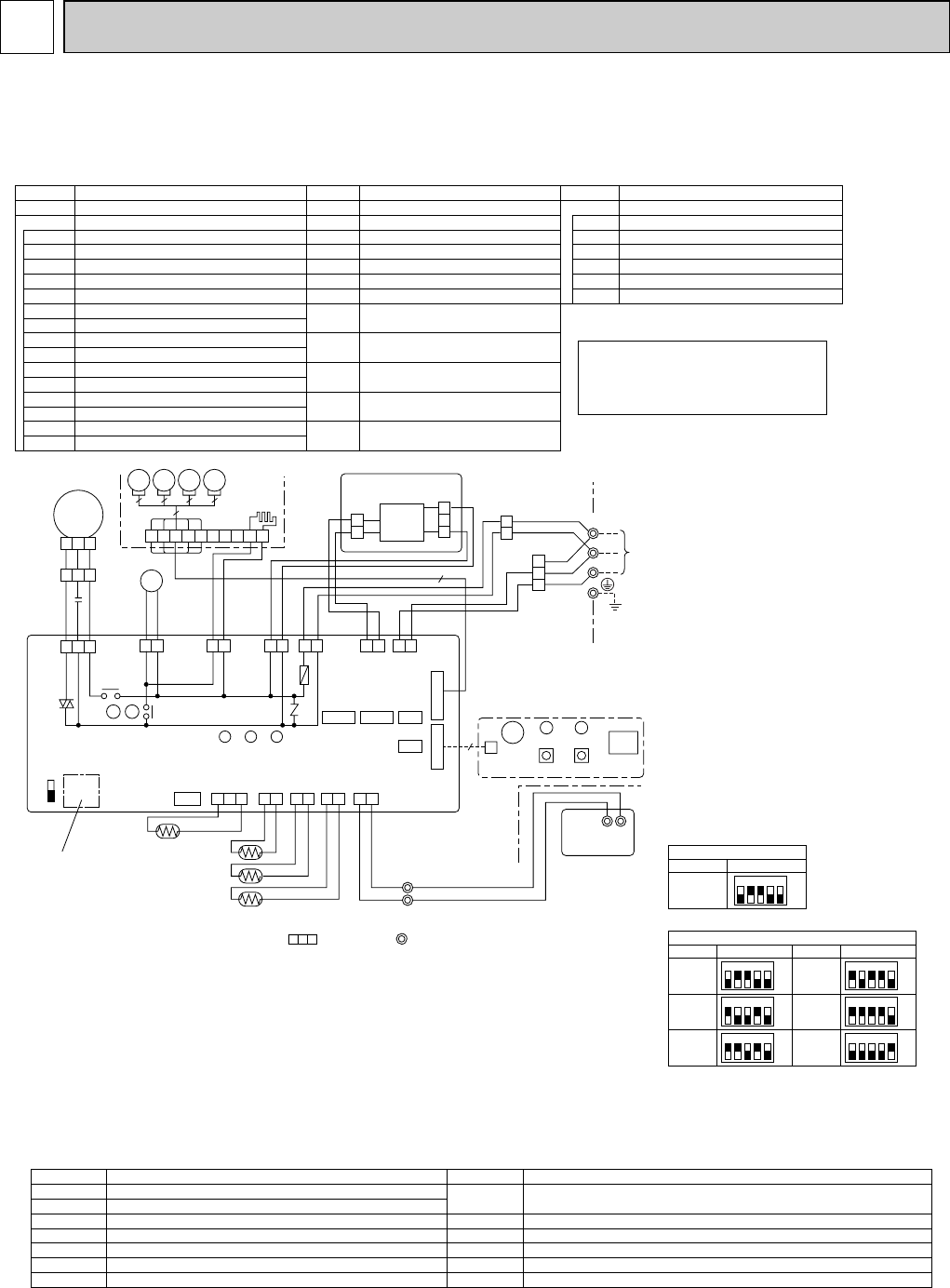
WIRING DIAGRAM
I.B
SWE
ON
OFF
SW2 SW1
Refer to tables 1 and 2
for service PCB.
HEATER
CN24
(
YLW
)
D.SENSOR
CN31
(
WHT
)
1 2 3
INTAKE
CN20
(
RED
)
1 2
LIQUID
CN21
(
WHT
)
PIPE
CN29
(
BLK
)
1 2
1 2
REMOCON
CN22
(
BLU
)
1 2
TH5
TH1
DS
TH2
2
1
TB5
R.B
TB6
12
TRANSMISSION WIRES DC12V
LED3 LED2 LED1
CN41 CN2L
CN51
CN32
WIRELESS
CN90
(
WHT
)
VANE
CN6V
(
GRN
)
W.B
BZ
CNB
RU
LED2 LED1
SW2SW1
9
5
5
1 31 2
BLK
BLU
BLU
WHT
BRN
ORN
POWER
CN2D
(WHT)
A-CONTROL
CN3C
(BLU)
1 31 31 31 3
ZNR
FUSE
WHT
RED
YLW
YLW
YLW
YLW
YLW
ORN
POWER
CNDK
(RED)
POWER
CND
(ORN)
D.U.M
CNP
(BLU)
DP
D.HEATER
CNC
(RED)
X4 X1
MV
GRILLE
FAN
(
WHT
)
1 3 5
1 2 3
1 2 3 6 7 4 8 9 5
10
BLK
WHT
RED
C
MF
X4
X1
BCR
1 2 3
3
2
1
CNSK
(RED)
2
1
CN2S
(WHT)
DC
13.1V
P.B
TO
OUTDOOR
UNIT
TB4
S1
S2
S3
YLW
ORN
YLW
ORN
BRN
5
5
MV
5
MV
5
MV
H2
Please set the voltage using the
remote controller.
For the setting method, please refer to
the indoor unit Installation Manual.
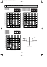
SW1
SW2
Table 1
Table 2
Service board
Service board
MODELS
PLA-A,AA
1 2 3 4 5
ON
OFF
1 2 3 4 5
ON
OFF
MODELS
PLA-A12AA
Service board
1 2 3 4 5
ON
OFF
MODELS
PLA-A30AA
1 2 3 4 5
ON
OFF
PLA-A18AA
1 2 3 4 5
ON
OFF
PLA-A36AA
1 2 3 4 5
ON
OFF
PLA-A24AA
1 2 3 4 5
ON
OFF
PLA-A42AA
w1
NOTES:
1. Symbols used in wiring diagram above are, : Connector, : Terminal (block).
2. Indoor and outdoor connecting wires have polarities, make sure to match
terminal numbers (S1, S2, S3) for correct wirings.
3. Since the outdoor side electric wiring may change, be sure to check the outdoor
unit electric wiring diagram for servicing.
4. This diagram shows the wiring of Indoor and Outdoor connecting wires
(specification of 230V), adopting superimposed system of power and signal.
w1. Use copper supply wires.
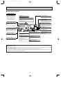
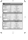
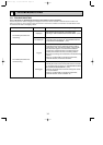
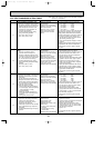
Check code
Symptom
Check code
Symptom
P1 Abnormality of room temperature thermistor(TH1)
Fb
Abnormality of indoor controller board
U*, F*
Abnormality in outdoor unit. Refer to outdoor unit wiring diagram.
FFFF
No corresponding unit
————
No trouble generated in the past
P2 Abnormality of pipe temperature thermistor / Liquid(TH2)
P4 Abnormality of drain sensor(DS)
P5 Malfunction of drain-up machine
P6 Freezing / overheating protection is working.
P8 Abnormality of pipe temperature
P9 Abnormality of pipe temperature thermistor / Cond. / Eva.(TH5)
E0-E5
Abnormality of the signal transmission between remote
controller and indoor unit
E6-EF
Abnormality of the signal transmission between indoor unit and outdoor unit
[Self-diagnosis]
1. For details on how to operate self-diagnosis with the wireless remote control, refer to the technical manuals etc.
2. For the wired remote control : When you quickly press twice the CHECK switch on the remote control,
the unit begins self-diagnosis, and Check Codes generated in the past appear on the display.
For check Codes and Symptoms refer to the table below.
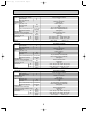
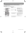
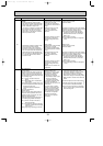
[LEGEND]
P.B
INDOOR POWER BOARD
SYMBOL NAME
I.B
INDOOR CONTROLLER BOARD
FUSE FUSE (6.3A/250V)
ZNR VARISTOR
CN2L CONNECTOR<LOSSNAY>
BCR FAN CONTROL ELEMENT
CN32 CONNECTOR<REMOTE SWITCH>
CN41 CONNECTOR<HA TERMINAL-A>
CN51
CONNECTOR<CENTRALLY CONTROL>
SW1
SWITCH <MODEL SELECTION>wSee Table 1.
SW2
SWITCH <CAPACITY CODE>wSee Table 2.
SWE SWITCH<EMERGENCY OPERATION>
X1 RELAY<DRAIN PUMP>
X4 RELAY<FAN MOTOR>
POWER SUPPLY<R.B>
LED1 POWER SUPPLY<I.B>
LED2
TRANSMISSION<INDOOR-OUTDOOR>LED3
C
CAPACITOR<FAN MOTOR>
SYMBOL NAME
W.B
WIRELESS REMOTE CONTROLLER BOARD
RECEIVING UNIT
BUZZER
LED<RUN INDICATOR >
LED<HOT ADJUST>
SWITCH<HEATING ON/OFF>
SWITCH<COOLING ON/OFF>
FAN MOTOR
VANE MOTOR
MF
MV
DEW PREVENTION HEATER
H2
DRAIN-UP MACHINE
DP
DRAIN SENSOR
DS
TB4
TERMINAL BLOCK<INDOOR/OUTDOOR
CONNECTING LINE>
TERMINAL BLOCK<REMOTE CONTROLLER
TRANSMISSION LINE >
ROOM TEMP.THERMISTOR
<32°F/15kΩ, 77°F/5.2kΩ DETECT>
PIPE TEMP.THERMISTOR/LIQUID
<32°F/15kΩ, 77°F/5.2kΩ DETECT>
COND./EVA.TEMP.THERMISTOR
<32°F/15kΩ, 77°F/5.2kΩ DETECT>
TB5,TB6
TH5
TH1
TH2
WIRED REMOTE CONTROLLER BOARD
R.B
RU
BZ
LED1
LED2
SW1
SW2
NAMESYMBOL
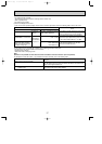
PLA-A12AA PLA-A18AA PLA-A24AA PLA-A30AA PLA-A36AA PLA-A42AA
PLA-A12AA1 PLA-A18AA1 PLA-A24AA1 PLA-A30AA1 PLA-A36AA1 PLA-A42AA1
OC370B--1.qxp 07.6.20 2:42 PM Page 12