


OPERATING PROCEDURE
PHOTOS & ILLUSTRATIONS
29
8
DISASSEMBLY PROCEDURE
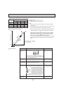
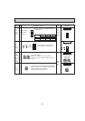
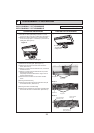
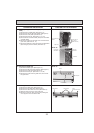
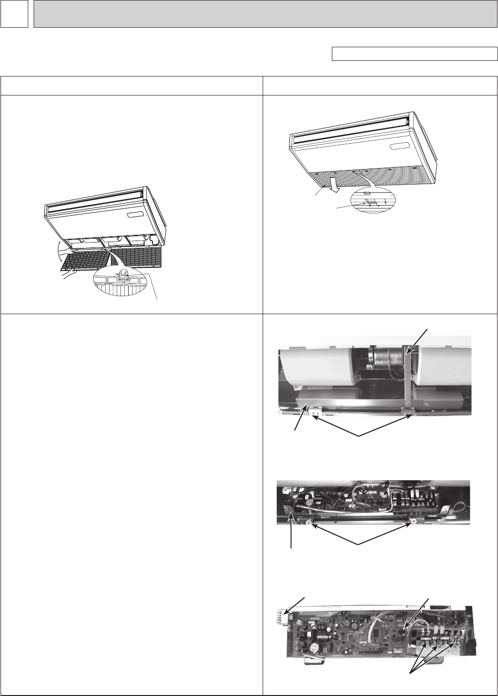
1. Removing the air intake grille
(1)
Slide the air intake grille holding knobs (at 2 or 3 loca-
tions) to the rear to open the air intake grille. (See Figure 1)
(2) While the air intake grille left open, push the stoppers
on the rear hinges (at 2 or 3 locations) to pull out the air
intake grille. (See Figure 2)
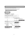
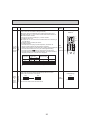
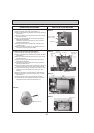
2.
Removing the indoor controller board and the electrical box
(1) Remove the air intake grille. (See Figure 1,2)
(2) Remove the screw from the beam and remove the
beam. (See Photo 1)
(3) Remove 2 screws from the electrical cover, and remove
the electrical cover.
(4) Remove 2 screws from the electrical box and pull the
electrical box downward.
Temporarily secure the electrical box using 2 hooks in
the back of electrical box.
(5) Disconnect the connectors on the indoor controller
board.
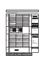
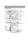
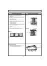
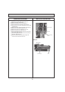
[Removing the electrical box]
(6) Disconnect the wires from the terminal blocks and pull
out the electrical box. (See Photo 2)
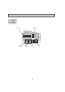
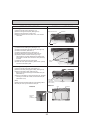
[Removing the indoor controller board]
(6) Remove the 6 supports from the indoor controller board
and remove the indoor controller board. (See Photo 3)
Figure 1
Photo 1
Photo 2
slide
Air intake grille
Air intake grille
holding knobs
hinges
Pull out the air intake grille
PCFY-P15NKMU-E PCFY-P24NKUM-E
PCFY-P30NKMU-E PCFY-P36NKMU-E
Figure 2
Beam
Electrical cover
Photo 3
Electrical box
fixing screw
Electrical box
Room temperature
thermistor (TH21)
Indoor controller
board (I.B.)
Terminal blocks
(TB2),(TB5),(TB15)
Be careful when removing heavy parts.
(Photo: PCFY-P36NKMU-E)
Electrical cover
fixing screws