


26
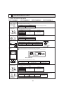
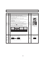
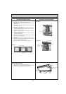
• To operate each indoor unit by each remote controller when installed 2 indoor
units or more are near, Pair No. setting is necessary.
Pair No. setting is available with the 4 patterns
(Setting patters A to D)
.
Make setting for J41, J42 of indoor controller board and the Pair No. of
wireless remote controller.
• You may not set it when operating it by 1 remote controller.
Setting for indoor unit
Jumper wire J41, J42 on the indoor controller board are cut according to
the table below.
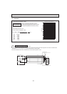
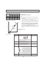
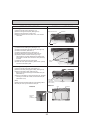
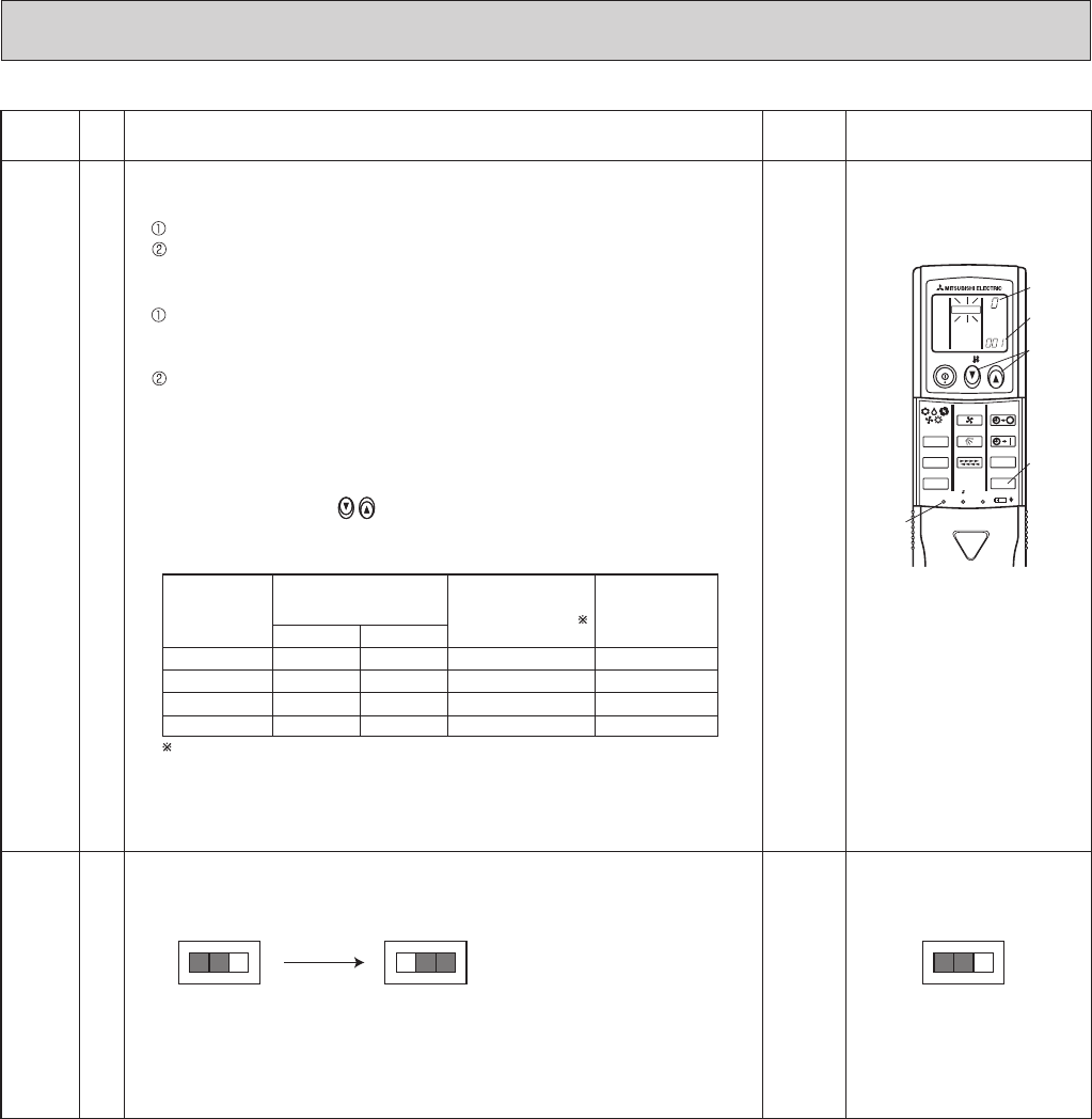
Wireless remote controller pair number:
Setting operation
1. Press the SET button (using a pointed implement). Check that the
remote controller's display has stopped before continuing.
MODEL SELECT
flashes, and the model No. (3 digits) appears (steadily-lit).
2. Press the MINUTE button twice. The pair number appears flashing.
3. Press the temperature buttons to select the pair number to set.
4. Press the SET button (using a pointed implement). The set pair number is
displayed (steadily-lit) for 3 seconds, then disappears.
J41, J42
Wireless
remote
controller
Pair No.
SWE
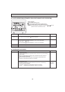
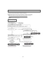
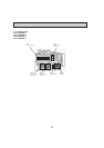
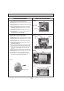
Test run
for
Drain
pump
(Option)
Connector Jumper
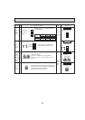
Drain pump and fan are activated simultaneously after the connector
SWE is set to ON and turn on the power.
The connector SWE is set to OFF after test run.
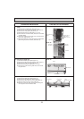
<Initial setting>
Pattern A
<Initial setting>
SWE SWE
OFF ON
SWE
OFF ONOFF ON
Under
operation
or
suspension
Under
operation
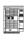
Setting pattern
J41 J42
Indoor controller
Jumper wire
Pair No. of wireless
remote controller
Factory setting
A
B
D
C
—
Cut
Cut
—
—
—
Cut
Cut
0
1
3
2
—
—
—
Pair No.4-9 of wireless remote controller is setting pattern D.
ON/OFF
TEMP
FAN
VANE
MODE
CHECK
LOUVER
TEST RUN
AUTO STOP
AUTO START
h
min
RESET
SET
CLOCK
MODEL SELECT
Model No.
Temperature
button
SET button
Pair No.
Minute
button
Switch Pole Operation by switch Remarks
Effective
timing